Click here to return to the home page.
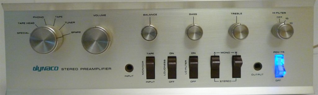
The PAT-4 was Dynaco's companion solid-state preamp for the Stereo 120. The PAT-4 pages have lots of information about it, starting with schematics. As you work your way through, you'll see:
The following links are a scan of a nice, clean copy of the PAT-4 assembly and user manual. The files are both kind
of big because the scans are high res. You can zoom in tight to see what-ever you need, since they were scanned at 300 dpi.
They even include the large fold-out diagram.
PAT-4 Assembly Manual, Part 1
PAT-4 Assembly Manual, Part 2
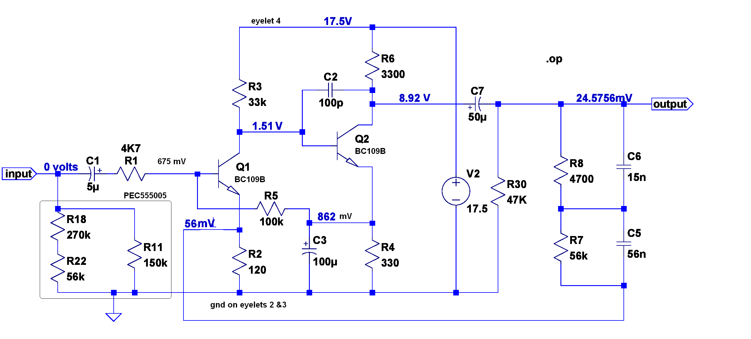
If your phono preamp is not working, a good place to start is with a check of the DC voltages. That was never listed in the manual, so I've prepared this figure with the no signal DC voltages on the nodes in the phono preamp.
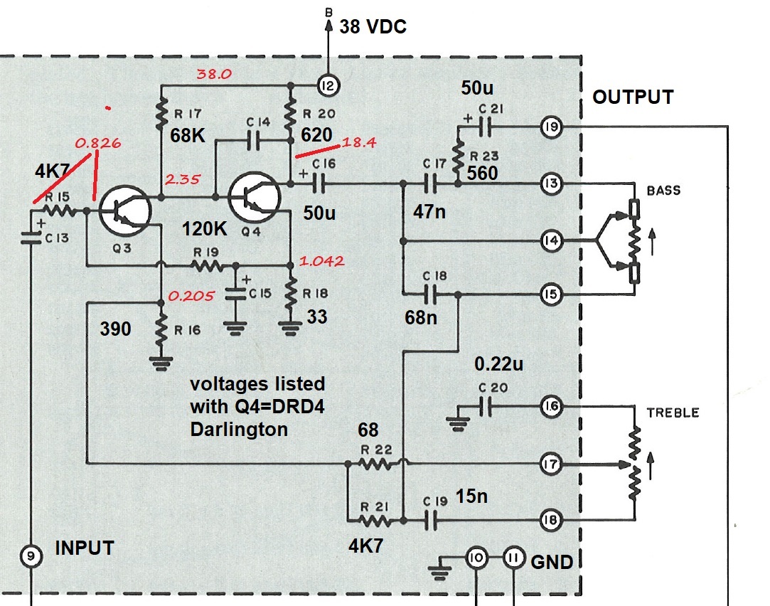
If your line stage is not working, a good place to start is with a check of the DC voltages. I've shown the voltages here with the DRD4 Darlington replacing Q4. For the stock Q4, the base voltage is 0.7 volts lower, but the rest of the voltages are very close to those listed here.
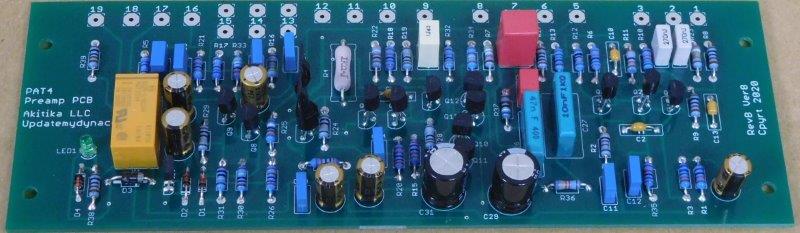
One of the PAT4Renewal circuit boards in assembled form
The number of PAT-4 Preamp upgrades has grown through the years, so I felt it was time to reorganize this page. Here's a short description of all of the upgrades, with a link to more information.
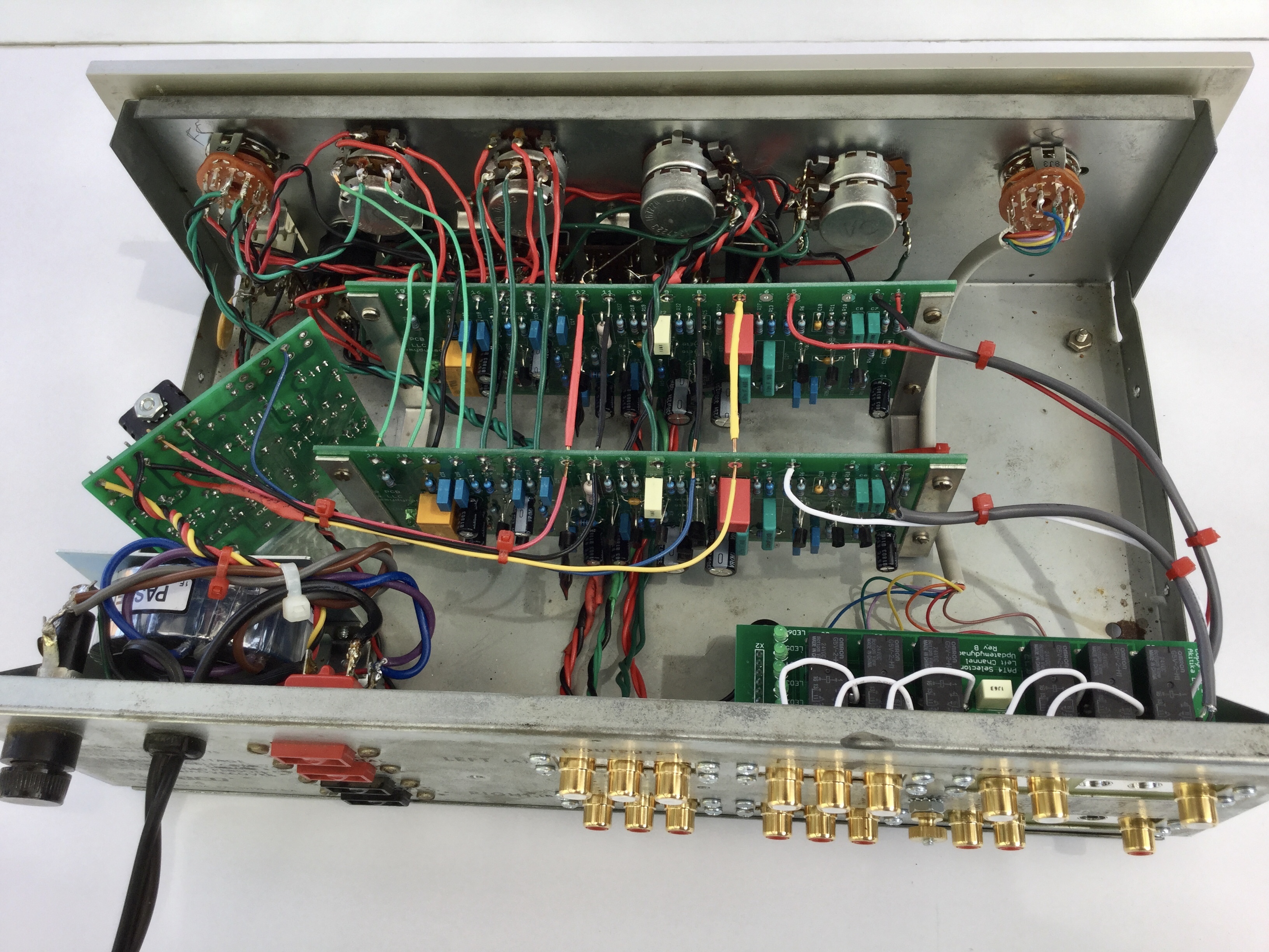
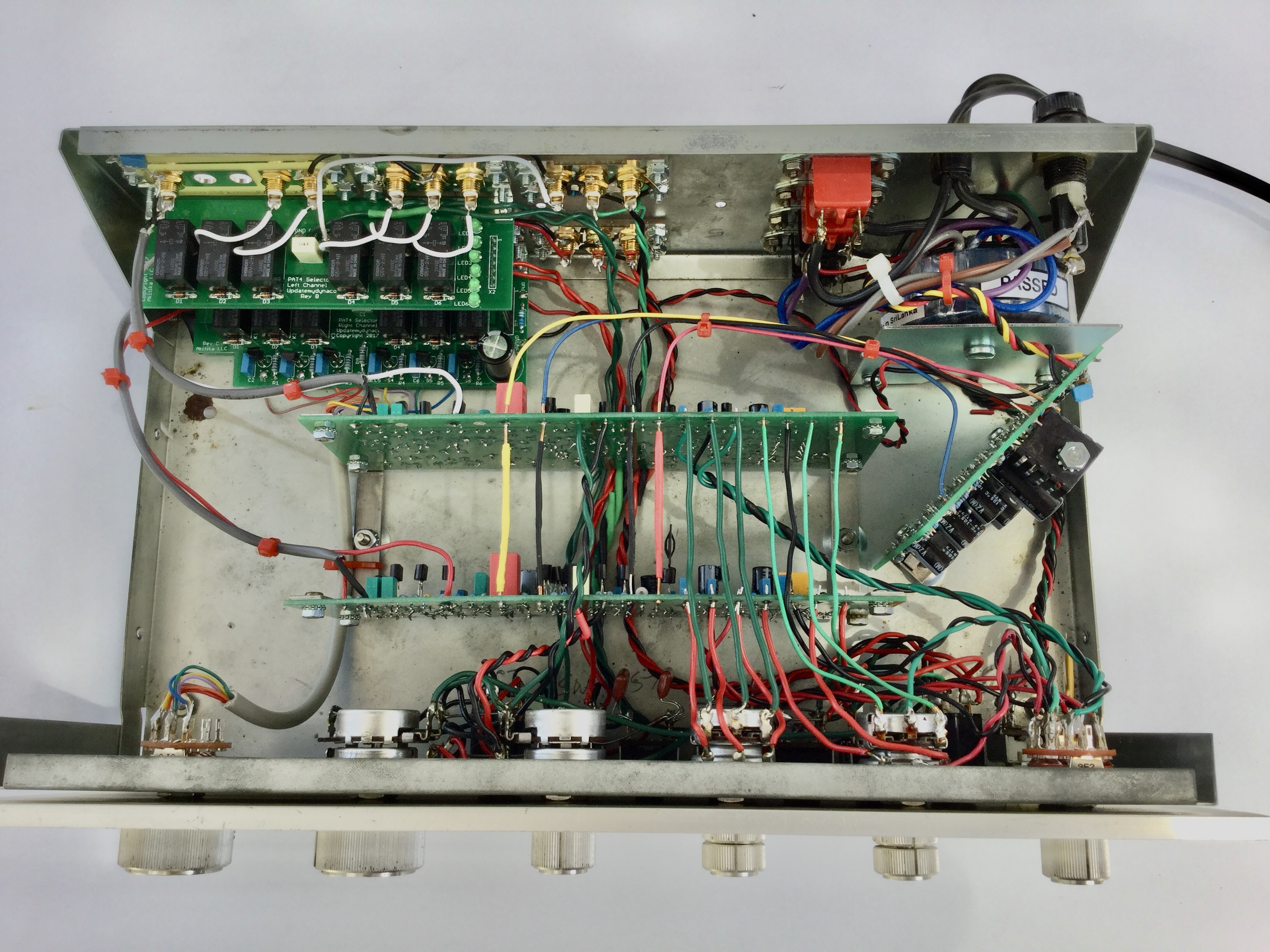
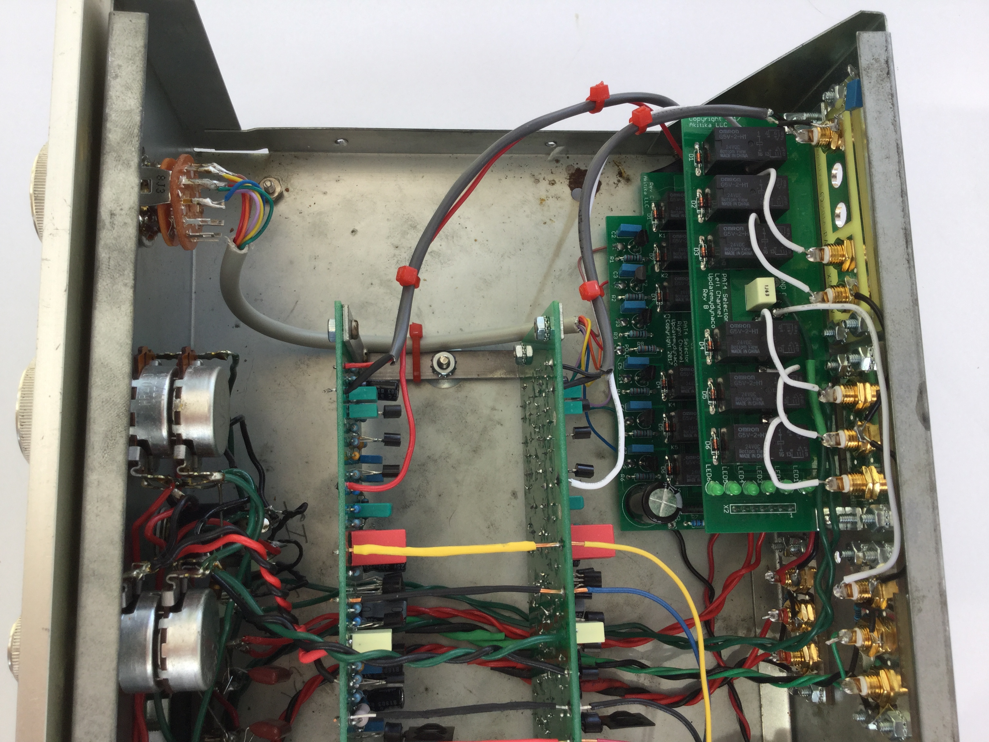
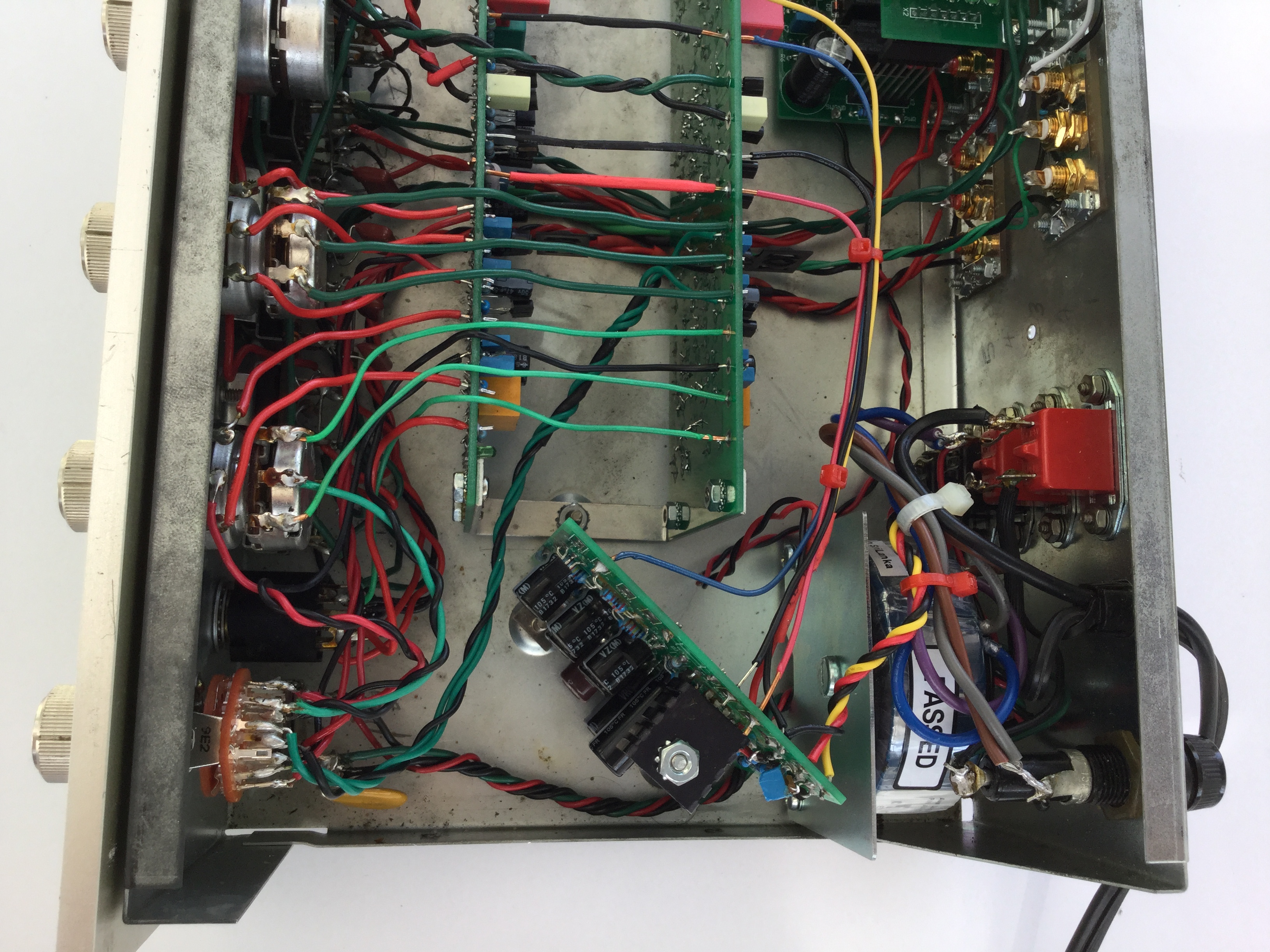
Here are a bunch of detailed pictures of a PAT-4 that has been upgraded about as many ways as possible. We just have links here, since they are big pictures, but if you click the links, you can see or download any of these pictures.
Although the tone controls have been undeservedly disparaged through the years, the unique Dynaco design makes the center position, +/-5% of the rotation absolutely flat. With proper adjustment, this takes the tone controls out of the circuit when in the 12 o'clock position. The next two items give information about the bass and treble controls, and how to assure that flatness.
The PAT-4 tone controls are "non-traditional". The traditional tone controls have the classic Baxandall topology. The PAT-4 tone controls are rather different, and a bit difficult to understand. Here's a link to David Hafler's patent #3,499,681 that covers the design of the tone controls.
The PAT-4 Bass Control potentiometer is unique in that Dynaco way. The document here shows how to make sure your control is centered for flat bass response, and how to clean the control. It also provides data about the rather unusual characteristics of the control. PAT-4 Bass Control Pot gives you everything you need to know.
The PAT-4 Treble Control potentiometer is also unique in that Dynaco way. The document here details a method that assures flat treble response when the control is centered. It also shows how to clean the control and provides data about the control's unusual characteristics. PAT-4 Treble Control Pot gives you everything you need to know about the treble pot.
You say you've already cleaned your pots with contact cleaner, but the bass control is still kind of scratchy. If so, it's very likely that C16 has become leaky. Its probably best to just replace C16, but theres an interesting leakage test you can perform:
C16 is originally 50 µF, but 47 µF is an equally fine replacement. It should have a working voltage rating of greater than or equal to 25 Volts.
Why does C16 become leaky? It sits right above R20, a 620 Ohm, 1 Watt resistor that dissipates about 640 mW. In most of examples Ive seen, C16 actually touches R20. The heat is probably the cause of the failure. Replacement caps typically have a bit smaller diameter, putting some space between themselves and R20. This should enhance the life of the new cap.
I've recently come across a source of New Old Stock (NOS) parts for the PAT-4. The bass and treble controls have special tapers as described above. I thought that they were not available anymore, but Vintag Electron has an Ebay store that, at least for now, is carrying some PAT-4 parts (bass and treble pots, rocker switches) that I haven't found anywhere else. I haven't checked any of the parts myself, but he has a great feedback rating, so his stuff is probably the real deal. Just follow the link, and put PAT-4 into his "Store Search" box.
You can guarantee that your tone controls are flat, or just have an easy way to compare a flat setting to a tone control shaped setting. You can add a tone control switch that replaces the HI FILTER switch that almost no one ever uses. I've almost finished working on a kit that adds a tone control disable switch to the PAT-4. You can optionally drop the gain of the flat gain stage a bit also...that can increase the SNR.
Switchable Tone Control Disable Installation Manual.
Buy the Switchable Tone Control Disable
The PAT-4 volume control pot is listed as 250K. I measured one in one of my PAT-4's. One track measured 194K. The other track measured 185K. Either these were a bit anomalous, or the real resistance of the pots was closer to 200K than to 250K. The loudness taps were both up 41K Ohms from the bottom of the pot. At rotational extremes, the wiper comes within about 40 Ohms of the ends of the pot.
These kind of volume control pots, with the loudness tap, are becoming somewhat scarce. One reasonable replacement actually comes from Radio Shack. It's their part number 2711732, a 100K Stereo Audio Pot. There are some differences:
| Parameter | Dynaco | Radio Shack | Comment |
|---|---|---|---|
| Total R section 1 | 185K ohms | 111K | |
| Total R section 2 | 194K | 100K | |
| R tap to gnd end 1 | 41K | 13K2 | |
| R tap to gnd end 2 | 41K | 13K9 | |
| Shaft diameter | 0.250 inches | 0.234 | Pretty close |
| Shaft type | D shaped | Round | Works fine |
| Bushing diameter | 0.375 inches | 0.266 | Radio shack needs washer |
However, as we used to say in the music business when tuning, "It's close enough for jazz". You may have to bend the locator tab off the Radio Shack part.
The original PAT-4 power supply was a beautiful compromise for a time and a world where transistors cost more than capacitors. The output voltages were fairly quiet, though completely unregulated. They would drift around with the line voltage, with the temperature of the transistors in the phono preamp and high level stages, when the refrigerator compressor kicked in...you get the picture! At high frequencies, its output impedance was low, but at low frequencies, the impedance was 1000's of Ohms. Power supplies, ideally, should have low impedance and low noise everywhere!
Now, at some point, people addressed the PAT-4 shortcomings by "throwing a mess-o-microfarads" at the problem. That made the power supply better, but still left rather high Z-out at low frequencies. Further, it still wasn't regulated. Low or high line conditions were still directly reflected in the output voltage. The effects of other appliances in the house turning on still came through the PAT-4 power supply.
The new PAT-4 Power Supply Kit adds electronic regulation to the power supply equation, along with enough microfarads to keep everything quiet. It's easy to build and install. Just remove the silver can cap, and mount the new power supply using the same mounting holes. It maintains a slow start so there are no clicks and pops even if you turn it on while connected to an energized power amplifier. All the output impedances are less than 1 Ohm, and the noise is almost too low to measure.
We also have re-designed and re-routed the transformer secondary wiring to decrease the loop area, which minimizes external fields caused by power supply ripple. For the rest of the details, please take a look at the PAT4PWR ordering information and Assembly Manual.
Gerhard, from New York, sent along these pictures of his PAT-4, with the PAT4PWR kit installed. Note the tight twist on the transformer wires which greatly diminishes external hum fields. Note also how Gerhard has dressed the wires and collected them with cable ties. The result is a PAT-4 that looks great and sounds great!
All the sound in the PAT-4 passes through the high level stage. If only there were a simple way to dramatically decrease the distortion, you could improve the whole preamplifier.
You can install our DRD4 Distortion Reducing kit, and drop the high level stage distortion by a factor of 10.
Here are some specifics: With 1 Volt RMS into a 100 KOhm load, the PAT-4 has about 0.02% distortion. That's pretty good, but it could be 10 times better! With the DRD4 kit you just change one of the stock transistors in both left and right channel high level stages, and you will drop the distortion from 0.02% to 0.002%. We supply the specially selected darlington transistors, heat-sinks and thermal compound. Of course, you get the usual easy-to-follow installation manual.
Distortion Reducer Installation Manual.
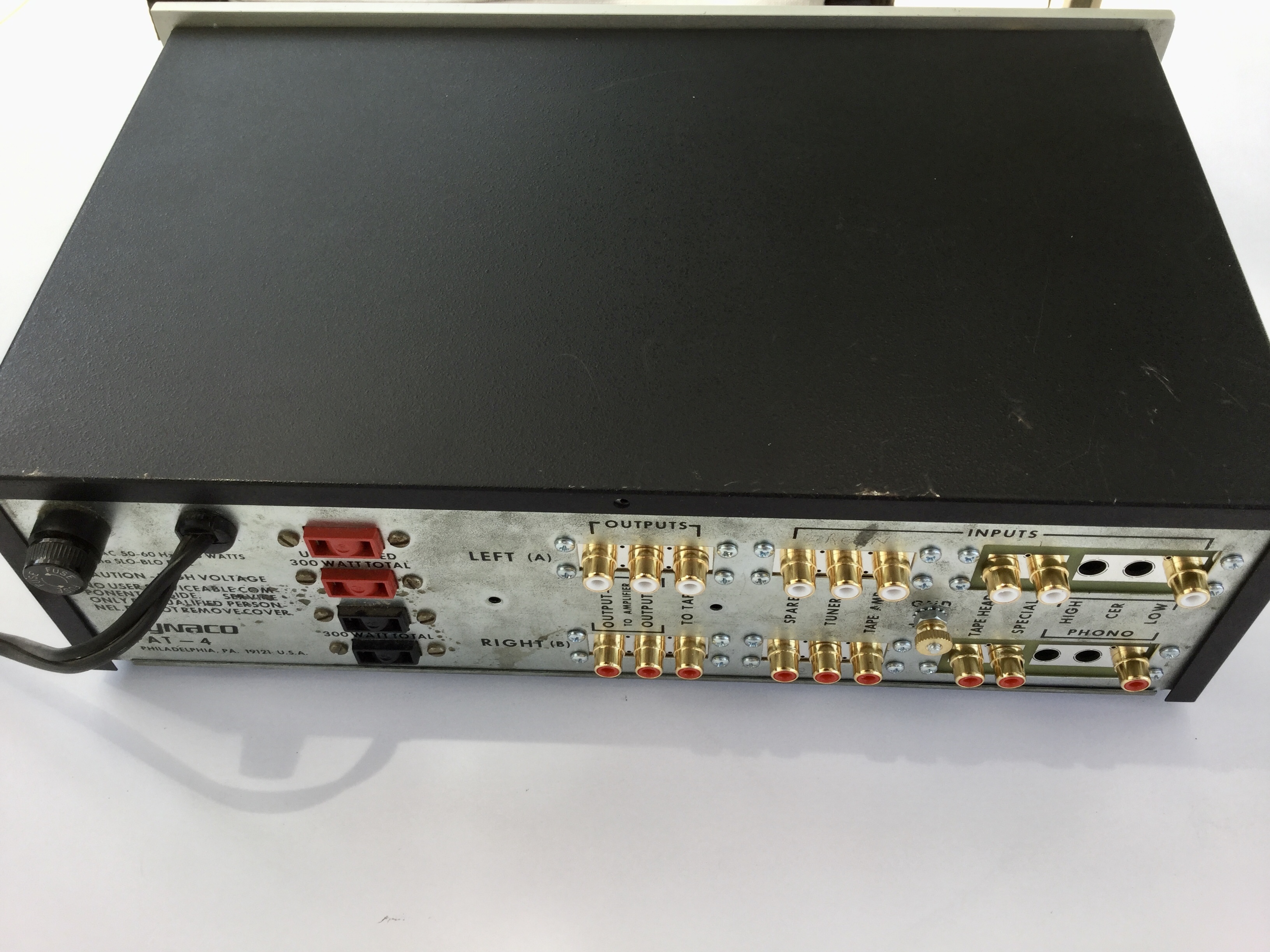
The PAT-4 has a six position input selector switch, 3 low-level inputs and 3 high-level inputs. Very few people use the Special and Tape-Head inputs. If you need more high-level inputs, you can convert them to accept high level inputs. The step-by-step instructions that follow were posted by Dr. Tinear to the AudioKarma forum. (Note: I haven't tried the modification myself). It is posted here with Dr. Tinear's kind permission.
Here are Dr. Tinear's step-by-step instructions on converting the PAT-4's Special and Tape Head inputs to line-level inputs. You'll need the PAT-4 Preamp pictorial wiring diagram to identify the switches and the lug numbers on each. The phenolic wafers on the selector switch are fragile, so be very careful when you shift wires or do soldering on that switch.
1. Remove the following wires at the rear panel:
- Short Lug 2-3 to Short Lug 4-5
- Short Lug 13-14 to Short Lug 15-16
2. Add the following wires at the rear panel:
- Short Lug 4-5 to Short Lug 6-7
- Short Lug 15-16 to Short Lug 17-18
3. Remove the following wires between the front SS wafer and the front PC-16:
- SS lug 4 to PC-16 eyelet 6
- SS lug 3 to PC-16 eyelet 7
- SS lug 2R to PC-16 eyelet 8
- SS lug 5F to PC-16 eyelet 1
- SS lug 2F to PC-16 eyelet 5
4. Remove the following wires between the rear SS wafer and the rear PC-16:
- SS lug 4 to PC-16 eyelet 6
- SS lug 3 to PC-16 eyelet 7
- SS lug 2R to PC-16 eyelet 8
- SS lug 5F to PC-18 eyelet 1
- SS lug 2F to PC-16 eyelet 5
5. Disconnect the wire from front SS lug 8 and connect it to front PC-16 eyelet 1.
6. Disconnect the wire from rear SS lug 8 and connect it to rear PC-16 eyelet 1.
7. Add the following wires from the front SS wafer to the front PC-16:
- SS lug 8 to eyelet 5 (do not solder at the SS lug)
- SS lug 8 (solder 2 wires here) to eyelet 6
8. Add the following wires from the rear SS wafer to the rear PC-16:
- SS lug 8 to eyelet 5 (do not solder at the SS lug)
- SS lug 8 (solder 2 wires here) to eyelet 6
9. Add the following wires at the selector switch:
- Front SS lug 5F to front SS lug 2F
- Rear SS lug 5F to rear SS lug 2F
10. (Optional) Remove the 7500 ohm resistor between AS lug 2 and AS lug 5. Replace it with a short length of wire, making sure that the wire does not contact any of the other switch lugs. This change gives you full A+B mono rather than 6 dB of stereo separation when you set both the A and B switches to Mono.
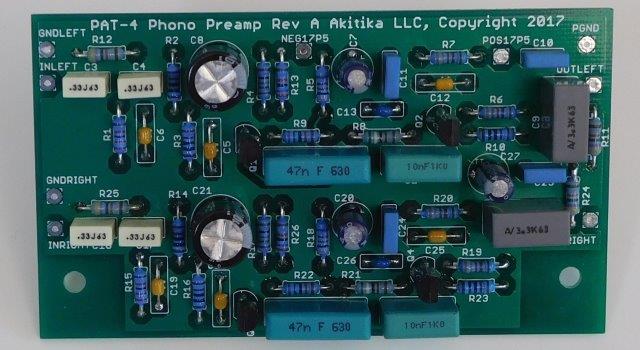
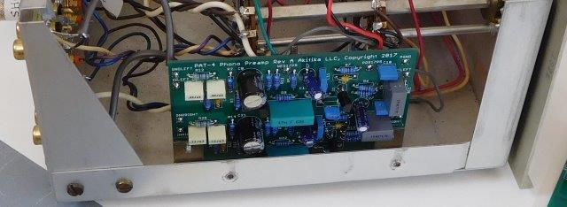
The PAT4LP kit was the original way to upgrade your phono section. If you like keeping an original look inside your PAT-4, that's probably the way to go. But, if you don't mind drilling two holes, you can add a brand new phono preamp circuit board and pick up a lot of advantages that come with the freedom in a new PCB design. Please note that this kit requires installation of the PAT4PWR improved power supply
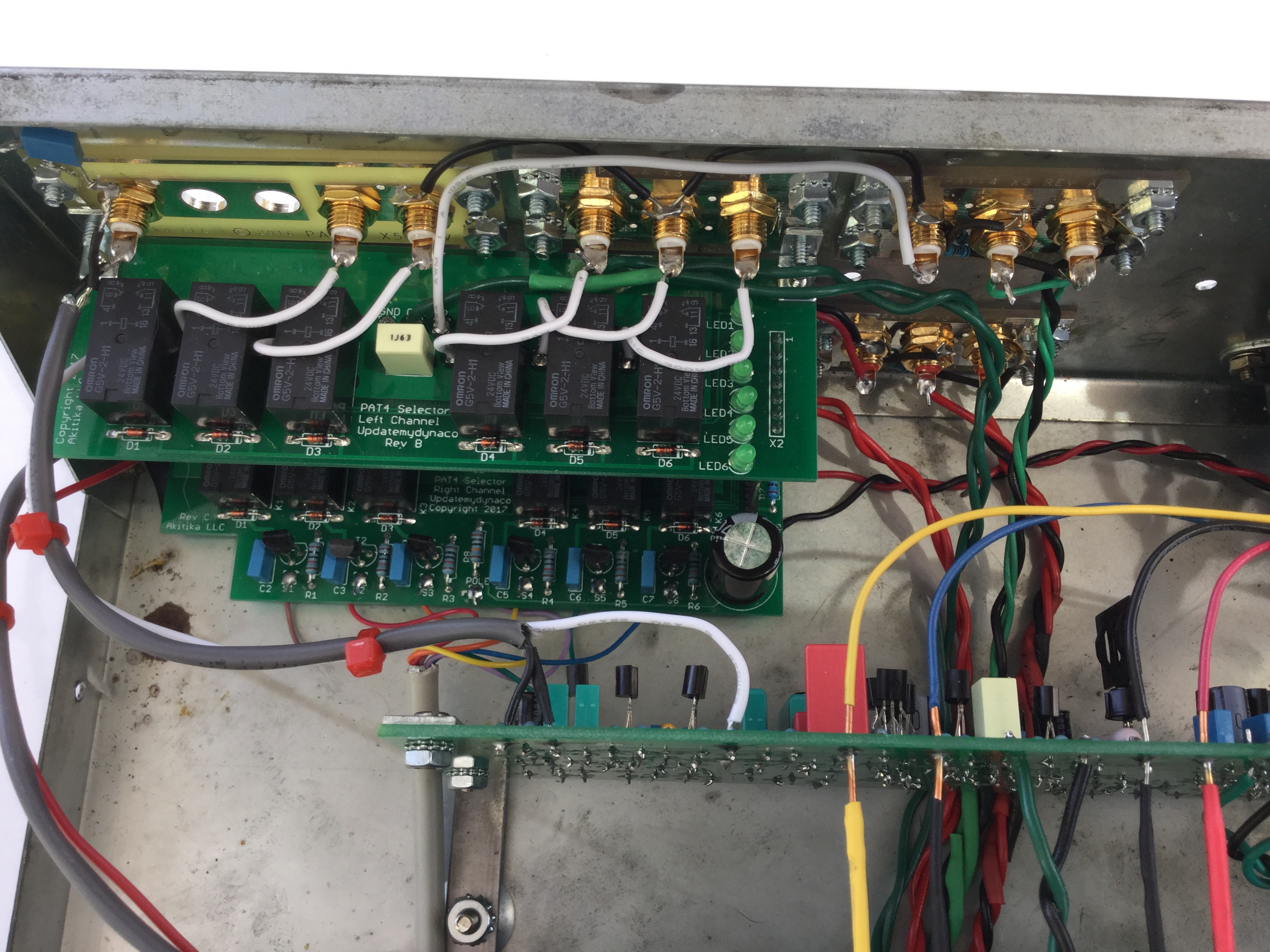
Here's a picture of the phono preamp, installed in a PAT-4, right near the selector switch
Order the PAT-4 Phono Preamp Replacement and Upgrade Kit
There are two complaints I have heard through the years about the PAT-4.
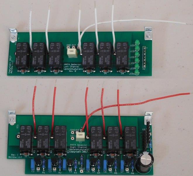
Of course, the selector switch could be cleaned, but sometimes the cleaning doesn't last very long. Even when working well, the lack of crosstalk attenuation means you hear the radio while you listen to quiet parts of records. Can't something be done about this?
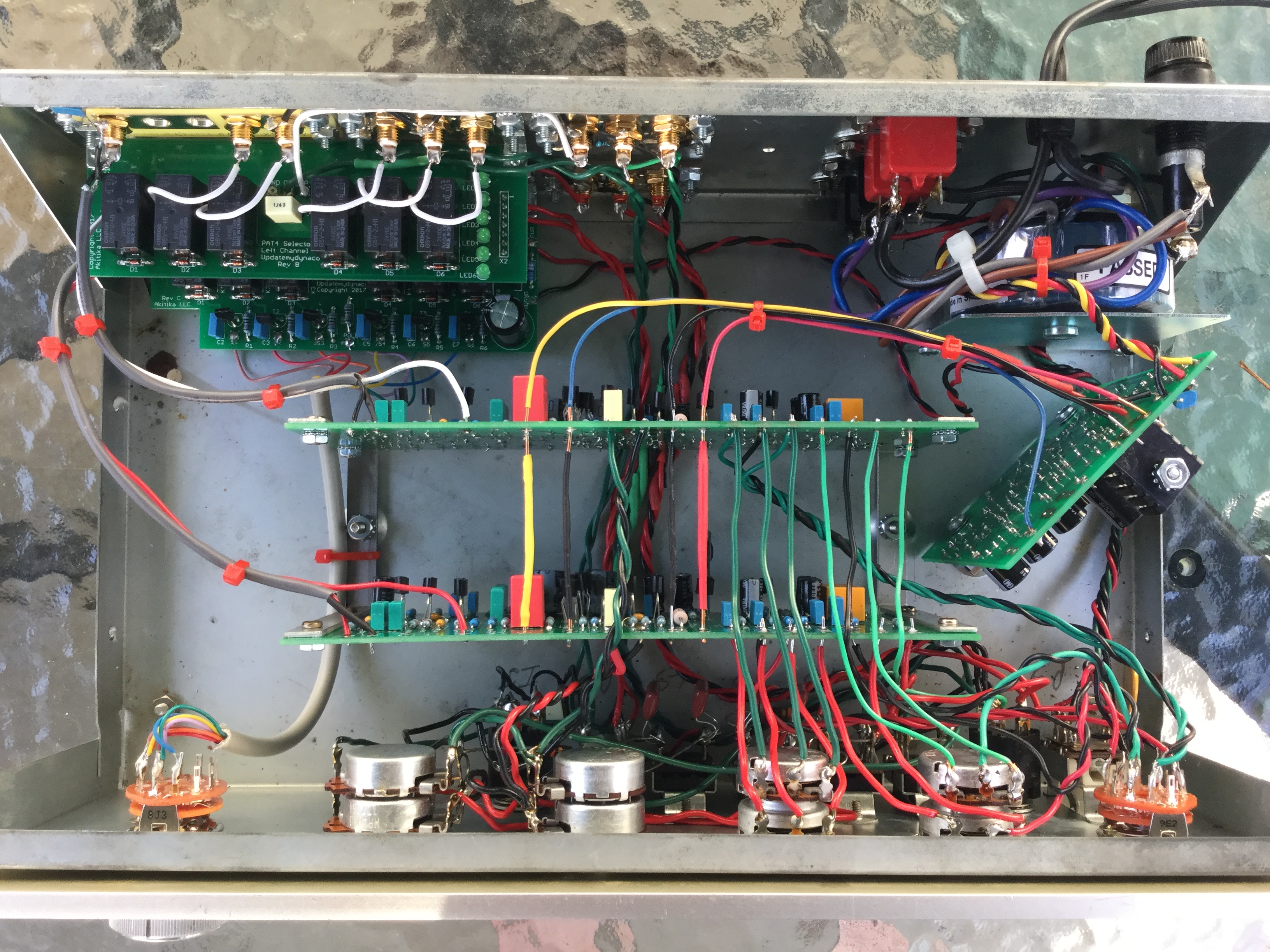
Heck yes! The improved selector switch has custom circuit boards with sealed relays. You'll never have to clean a contact! And owing to careful design and layout, the crosstalk is between 33 and 100 times lower than the original selector switch. All the selection gets done within an inch of where the signals enter the PAT-4, so we've dramatically reduced the chances for undesired crosstalk. We've even included special drive circuits to minimize interference between relay drive signals and the audio path. The result is much less noise and crosstalk, and much more reliability.
A few caveats:
Order the PAT-4 Selector Switch Upgrade Kit
Factory built units have date stamps inside the chassis, between the circuit boards and the back panel, on the floor of the chassis. One of mine says, "SEP 78". I'll be so bold as to generalize this to say all factory assembled PAT-4's have a 3-letter month code and a two-digit year code identifying their date of manufacture.
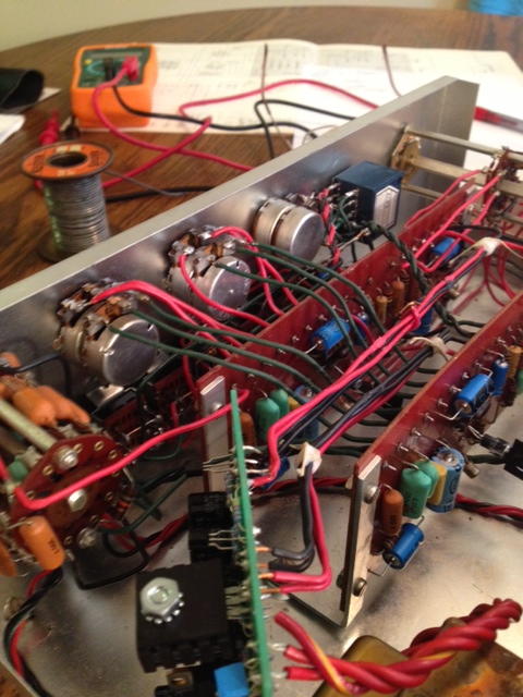
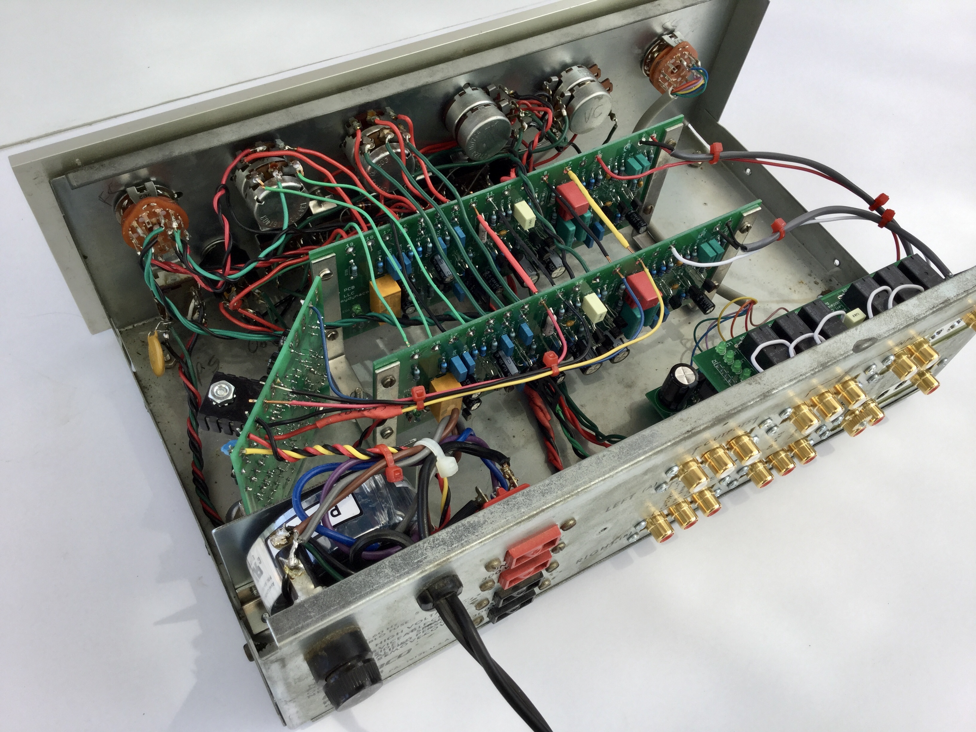
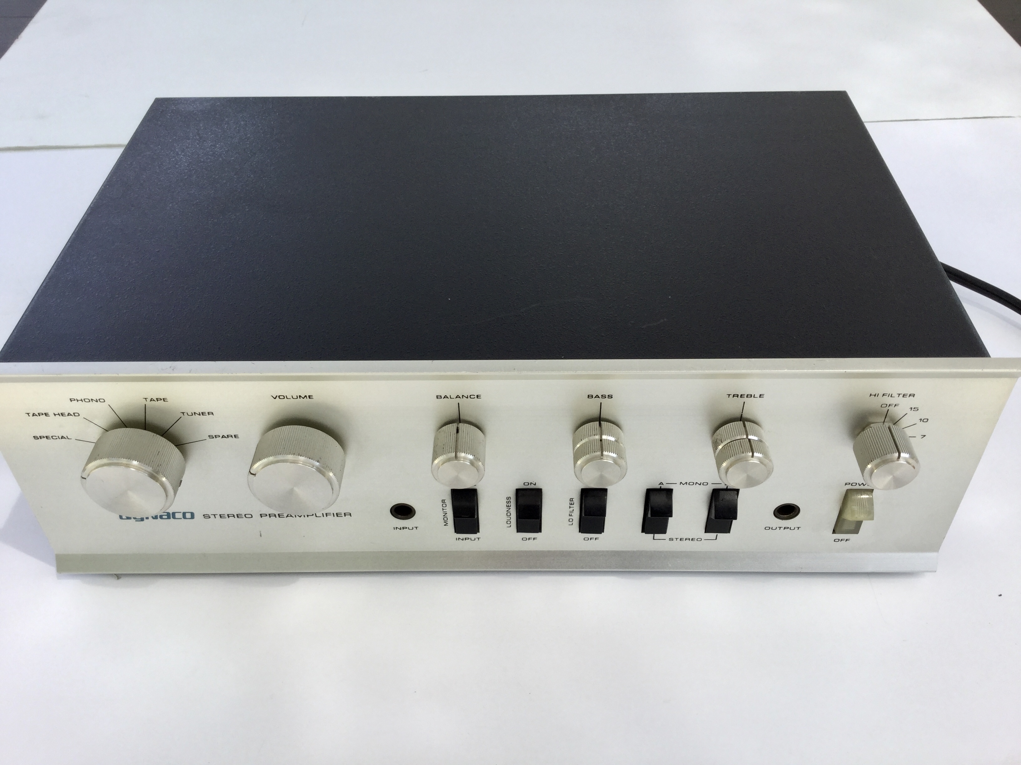
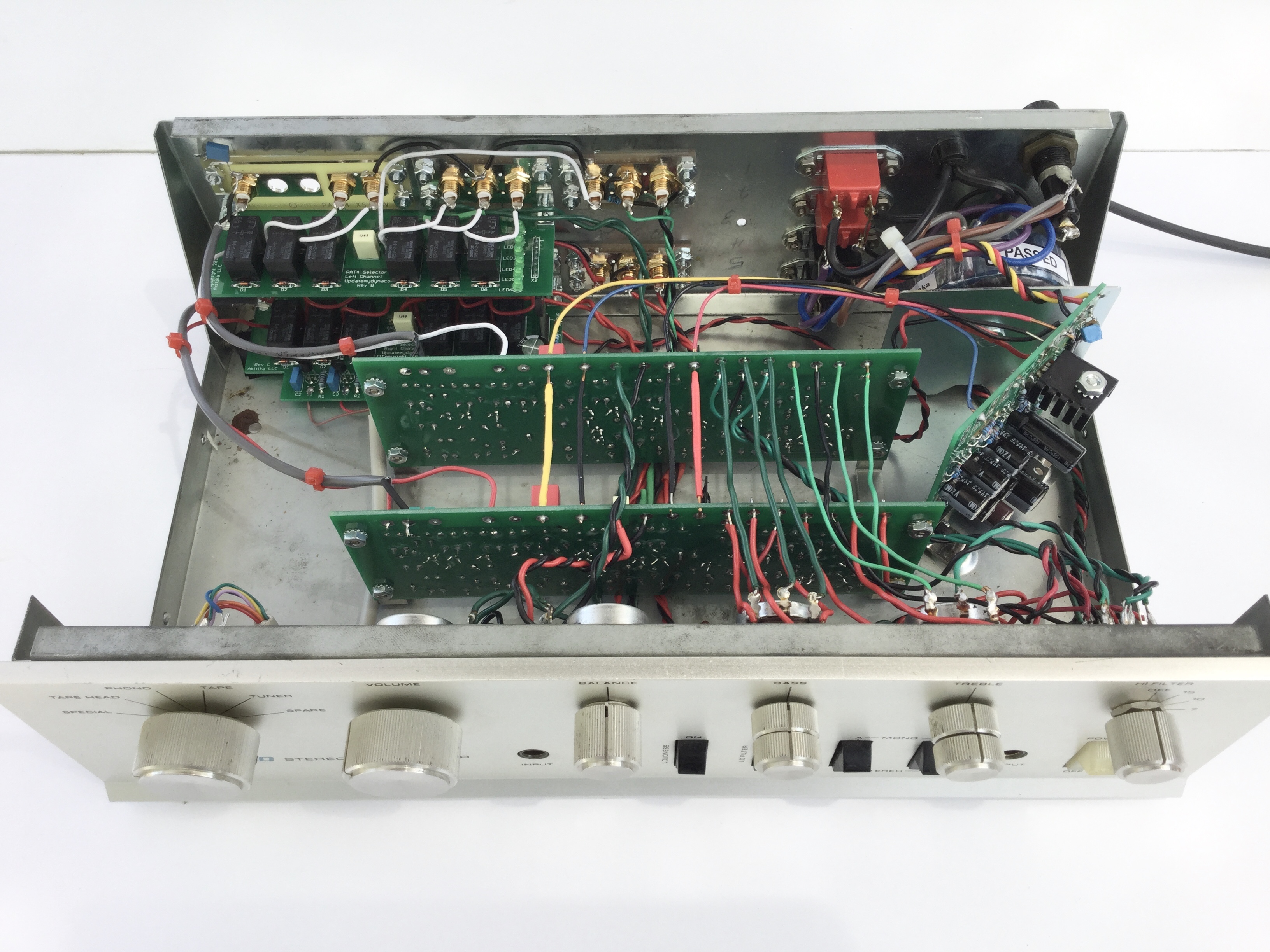
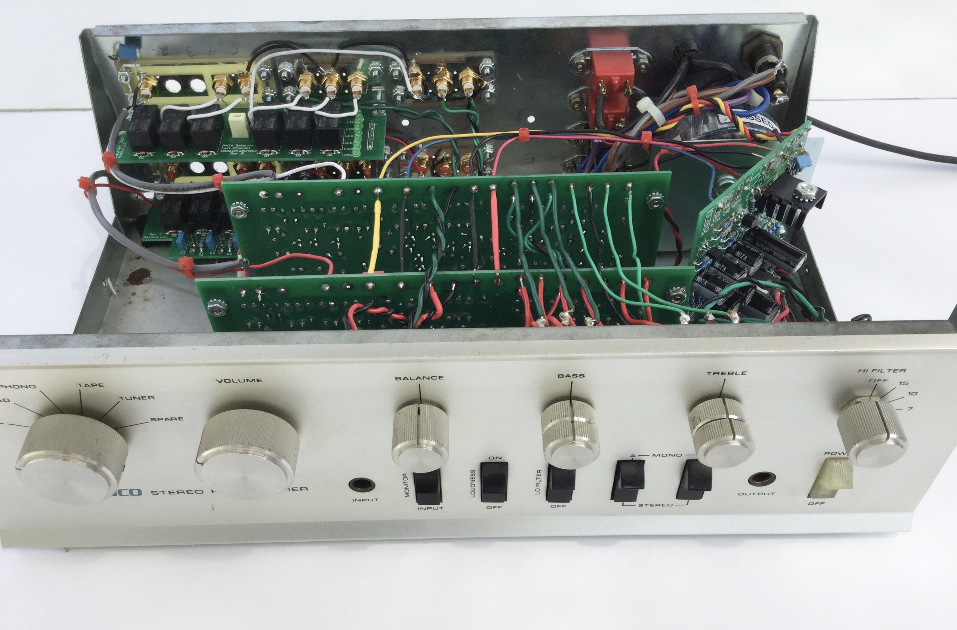
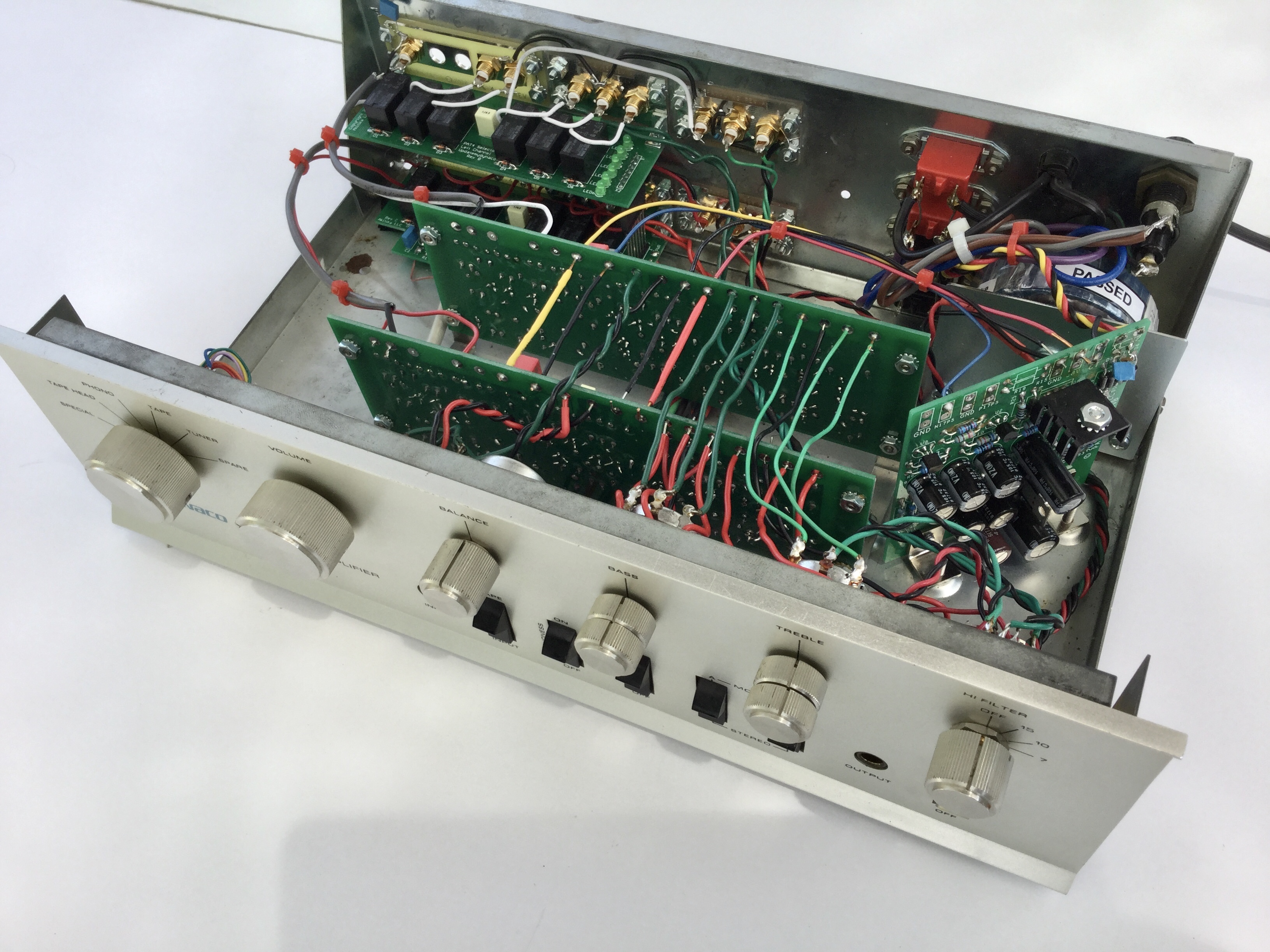
Hello Dan ... After 35+ years hidden and forgotten in storage, I recently rediscovered a treasure trove of vintage stereo and test equipment from the late 60's & 70's. To my surprise, all of the Heathkit test equipment and most of the vintage stereo systems from Marantz, Harman Kardon, Dynaco, Thorens, Shure, Janszen, LWE ... to list a few, were still in good working condition and capable of further upgrading and tweaking. Part of the upgrading involved modifications to an old classsic ... the Dynaco PAT-4, which I had earmarked to be part of a recently setup electronics work bench. Photo attached. My original plan for the PAT-4 was to upgrade its performance while maintaining its original front panel functionality and internal wiring layout. Since the availability of quality electronic components in Canada is very limited, I turned to suppliers in the US, and was fortunate with the help of Google to have located your updatemydynaco.com website. To my surprise, you had already worked out, tested and made available in kit form all of the performance updates I had in mind. To minimize damage to the original wiring, the upgrade & tweaking of the Dynaco PAT-4 were carried out in three separate stages/steps and tested, with their noted performance results.
Step 1: Replacing the original unregulated iron-core transformer/rectifier/capacitor power supply with a toroidal transformer + a fully-regulated power supply (PAT4X + PAT4PWR Kits). Result: A very audible improvement in the S/N ratio and the complete absence of hum.
Step 2: Replacing selected components (resistors, capacitors & transistors) in the line-stage of the original PC-16 circuit board with new low-noise resistors, capacitors and transistors (P4LSRC + DRD4 Kits). Result: A measurable and audible improvement in both HD/IM distortion and quality/accuracy of sound reproduction with a notable absence of listener's fatigue at higher volume levels. A huge overall improvement in sound quality. This upgrade involved the most work, but was well worth the effort.
Step 3a: Replacing/bypassing the original phono section of the PC-16 circuit board with a PAT-4 Replacement Preamp Board (PAT4PPR Kit) + replacing the old corroded & oxidized RCA jacks + chassis grounding screw with new gold-plated ones (PAT4RCAGG Kit). Result: Preliminary results are in keeping with a very low-noise, surgically-clean phono preamp with an outstanding transient response most evident when reproducing complex passages of classical music. I will eventually get around to running a listening comparison with my reference Marantz/Crown/Janszen/Polk/Thorens/SME/Ortofon turntable setup.
Step 3b: Before replacing the cover ... all potentiometers, rocker switches & rotary switches should be thoroughly cleaned. This will eliminate any annoying noises and intermittent malfunctions, such as channel cut-outs, transient distortion, etc. First, using blasts of compressed air, thoroughly blow away all dust from in & around the controls. Next, using a good quality, rapid-evaporating contact cleaner, e.g., MG Chemicals Electronic Contact Cleaner with Silicone, sequentially squirt the cleaner into the openings of each of the switches & controls while activating them several times. This type off contact cleaner will clean, lubricate & protect the contacts from further oxidation. For this general cleaning of all the controls, it would be advisable to avoid using a more powerful chemical-reacting deoxidizing cleaner, e.g., Deoxit ... reserving this type of cleaner for specific and more difficult/problematic cleaning jobs. Result: Smoother-functioning controls and freedom from erratic noises or channel dropouts.
The upgraded/refurbished Dynaco PAT-4 was paired with a tweaked "Universal Tiger" power amp (a modified Dan Meyer design) from the early 70's which survived the ravages of time, being custom-built with computer-grade components and weighing in at a hefty 30+ lbs/channel!!. I am considering the construction of a smaller form-factor power amp which could fit on the shelf below the PAT-4. Since, I do not own any of the Dynaco series of power amps for upgrading, the next viable option would be to purchase/build the Akitika GT-101 power amplifier kit. The published specifications are impressive, matching the performance of the refurbished PAT-4. I shall be soon placing an order for a GT-101 power amp kit.
Parting Comment: Dan, I must commend you on your dedication & commitment to not only restoring, but also to significantly improving the performance of selected vintage stereo equipment from the 60's & 70's ... giving them a new lease on life and saving them from the landfill. Very few experts or companies in the audio field will go to the lengths you have gone through to make the refurbishing/updating process so user-friendly & affordable. The only other person I could think of is David Jenszen of Janszen Electrostatic Speakers, who, to keep his father's electrostatic speaker inventions & legacy alive, provides in-house factory rebuilding for all earlier models, or for the do-it-yourselfer, impossible-to-obtain parts, e.g., a vastly-improved, replacement transformerless solid state 1,100 volt power supply, and also, detailed expert email advice for accomplishing improved performance.
Wishing you continued success in all of your future endeavors.
Dr. Joe
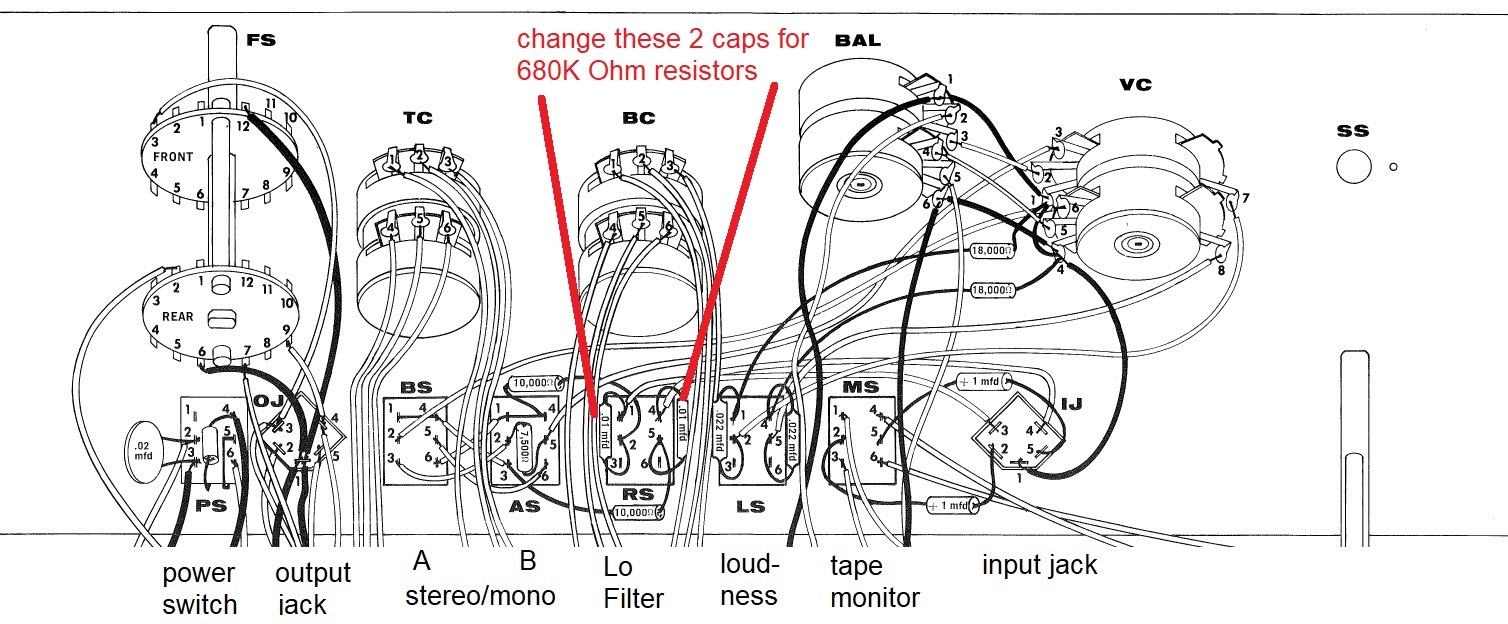
Do you ever use the LO filter? Its job, when activated, is to filter out some of the low frequencies. It may be useful if your source has a lot of hum or low frequency noise. I can probably count the number of times I have used the switch on the fingers of one hand. You can change its function to something that may be rather more useful.
You can change the LO filter to a 20 dB attenuator. Here how it's useful:
Converting your LO filter to a 20 dB attenuator is easy. You'll just swap two capacitors for two 680K Ohm resistors as shown in this picture. The resistors could be anything in the neighborhood of 680K, plus or minus 10%. However, they should be matched pairs. 1/4 Watt metal film resistors would do just fine.
Update to this Experiment -- While some of the things here are certainly valid, the biggest single thing that you can do to reduce the hum is to install the PAT4PWR board. It has lower hum at the output. More importantly, it handles the AC rectifier voltage in a much better fashion, dramatically decreasing the loop area of the rectified currents. This makes a HUGE decrease in the reported hum levels in a PAT-4.
You can also reduce hum with the PAT4X kit. It replaces the original transformer with a low-noise, low external field, toroidal transformer. But, you can also spend less money, and get some worthwhile improvements...read on!
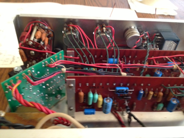
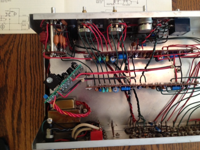
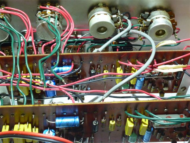
I'm trying to reduce the noise, both hiss and hum, in a PAT-4. The first picture shows the original circuit board. The second picture, a bit of the disassembly process. Note the tags on the wires to help it all go back together!
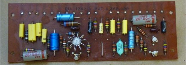
unmodified PAT-4 circuit board
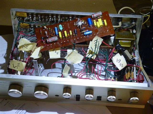
disassembling a PAT-4, tagging and removing the wires
We're back together again. I changed out a noisy 390 Ohm resistor in the emitter of the rigth channel tone control circuit, and dropped the broadband and 1/f noise by about 8 dB! That was one noisy resistor. The observation came about because both channels were not equally quiet.
If you have some extra hiss in your high level stage, you might get equally lucky with a "rifle-shot", changing out that 390 Ohm resistor. Still, to get it out, you have to disassemble your PAT-4 and pull the PC boards. Heck, while you're at it, why not replace all the resistors and electrolytic caps in the high level stage? You can do that with the P4LSRC kit.
The next experiment showed that with the volume control at minimum, the twisted pairs from the balance pots to the tone control amplifier inputs were kind of sensitive. With the cover off, and the system hooked up, touching your fingers to the insulated wire of the twisted pair adds audible buzz. I replaced the twisted pairs by legitimate shielded cables with a foil shield and a drain wire. You can now touch the outside of the shielded cable without picking up added buzz. This mod cut the hum reading by about 1/2 (I did this experiment at home, where my instrumentation is a bit crude). Hum usually comes from many contributing sources, all of which must be eliminated. This mod eliminated some of the hum, and will be maintained. But there's still more hum to find and remove. The pictures below show the shielded cable modification.
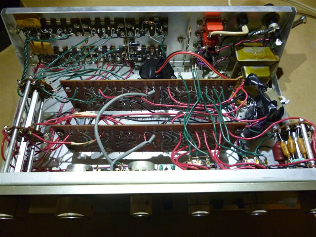
we changed twisted pairs to shielded cables from balance control to amplifier boards (viewed from the front)
back view of the mod, changing twisted pairs to shielded cables from balance control to amplifier boards
This document describes the process of preparing the ends of the shielded cable. You may also find that it's worthwhile to use shielded cables from the input jacks to the selector switch. The shield should only be connected at the input jack end.
As our first goal, we're trying to get a PAT-4 with the volume control at minimum, running into an updatemydynaco stereo 120 (voltage gain of 21), so free of hum that you can put your ear up to the speaker, and hear just hiss, and no hum. Let's see what this might really mean. 1 Watt into a typical speaker produces an SPL of 90 dB at 1 meter. If we put our ear about 0.1 meter from the speaker, then the SPL is about 20 dB more, or 110 dB. To get to the threshold of hearing, we need to drop the SPL to 0 dB. That says that the hum power in the output of the power amp has to be 10 pico-watts. That's 9 microvolts at the output of the amplifier, or 9/21=0.42 uV at the output of the preamp. Since the preamp also has a gain of 10, that means we'd need to pick up less than 0.042 uV of hum at the input of the preamp. Wow!
Now perhaps I'm a factor of 10 too generous with my power and ear sensitivity assumptions, so maybe we could really stand 1.37 uV of hum at the preamp's output. Measurements of preamp hum to date show around -100 dBv , or 10 uV. We're really shooting for -120 dBv...in round numbers, 1 uV of hum at the preamp's output. That won't be easy with the PAT-4's gain of 10 stage preceded by a volume control! We hope to report on today's experiments shortly.
My most recent experiment drove the noise (hum) floor way down, with any harmonic of hum driven to the white noise floor or below. I fed DC from an external power supply to the first capacitor after the rectifiers. I did not feed AC power to the internal power supply transformer. These steps are necessary, but are not sufficient.
The PAT-4 still picks up stray external magnetic hum fields. Next, I placed a 0.062 inch thick sheet of very high permeability mu-metal, Co-netic AA, on top of the PAT-4. The sheet was a bit wider than the footprint of the PAT-4. As Emeril would say, "BAM"...the harmonics were gone. That mu-metal is too expensive for most applications, so my next experiments are to see how much less mu-metal we can get by with, and to verify the hum killing experiment in a real listening test.
The experiments on this page started me thinking about and researching ground, hum and noise problems. When I think, I write...it's a way to sort things out, and preserve them for my future self. You may find it interesting also. Download the Library of Grounding Problems.
Here's a good way to figure out beyond a doubt if the balance problem is in your PAT-4, or the associated equipment. Trouble Shooting Balance Problems.
I have a kit that replaces the balance control. It's not an exact match, but it works pretty well. I haven't put it on the website yet. It's the PAT4BCR (balance control replacement) kit. The cost is $10.00. Send me an email and I can send you an invoice to cover the cost (and postage).
It seems no one really likes the PAT-4's tone controls. In addition, the gain stage typically has more gain than it needs, resulting in more hum and noise. This is especially so if you've updated your Stereo 120 with the Updatemydynaco amplifier modules, as they are 3 dB more sensitive than the original modules. If you're interested, you can download PAT-4 Improvements.