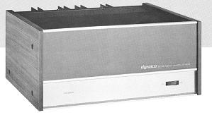
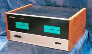
The Stereo 150


About the Stereo 150
By the time the Stereo 150 came out (around 1975), the venerable Stereo 120 had been in production a relatively long time. To modern eyes, the Stereo
120 would probably look a bit baroque. The Stereo 150 is a design that bears a strong resemblance to current day designs. Even so, certain
common features of current day designs are missing.
- PC-36 versions used a resistive load and bootstrap capacitor in the voltage amplifier stage
- PC-43 versions used the more modern single transistor current source as the load for the voltage amplifier stage
- Neither version used a current mirror to turn-around the input differential stage
- Neither version used any input stage degeneration resistors, which gives it a slow (by modern standards) 5V/us slew rate
Replacing and Upgrading the Power Supply Capacitors
You can replace and upgrade the power supply capacitors in the Stereo 150. Take a look at this manual that describes the process.
Replacing and Upgrading the RCA Jacks
Forty years or more can really do a number on the RCA jacks. Your original RCA jacks are probably quite oxidized. That makes it hard to get good ground and signal connections. You can upgrade your
RCA jacks to gold plated RCA jacks.Take a look at the manual that describes the process.
Lesser Known Facts About the Stereo 150
- That there are two versions, distinguished by whether the amplifier board is either the PC-36 or the PC-43
- The amplifier channels could be paralleled to produce a more powerful single channel amplifier. The manual quotes 150 Watts into 8 Ohms.
At first
this was confusing, because based on the +/-50 Volt rails, output power would max out at a theoretical 156.25 Watts into 8 Ohms. One of my
customers, Mitchell, was kind enough to correct me on this point. A careful re-reading of the manual shows that upon converting to parallel
mode, the power supply is also strapped to increase the B+ and B- from +/-50 to +/-63 Volts DC. That's enough to get to 150 Watts into 8 Ohms
with some room to spare.
- Speaker fuses were a part of the output protection scheme
- It used a thermistor on the input that would decrease the amp's sensitivity if the output heatsinks got too warm
Schematics and Assembly Manuals
Hints for Working on the Stereo 150
- At first, it looks hard to get to the amplifier modules to make troubleshooting measurements. Here's the secret. .
Four screws hold the back panel into the chassis: 1 screw in the left side panel, 1 screw in the right side panel, and
2 screws go thru the chassis bottom into the back panel. If you remove those 2 screws in the bottom, the back panel
rotates flat (if you prop the amp up so that the heatsink doesn't get in the way). This lets you easily work on the
amplifier modules
- A common failure mechanism if you're working on a Stereo 150 is that the one of the wires that connect to the amplifier
boards will break. Why? Dynaco made the interesting combination of the rotating back panel and really stiff solid wire. The
combination leads to broken wires.This is especially true if the original builder nicked a wire while stripping it.
Facts and Measurements from My Stereo 150
Through the miracle of Ebay, and a very reasonable "Buy It Now" price, I now (11/30/2013) have my very own Stereo 150. Here are some
quick thoughts and observations.
- The big filter caps are 10,000 uF @ 80 Volts; They are 2 inches in diameter, and their cases are about 4.125" tall.
- My amp is the earlier one, based on the PC-36 version of the amplifier PC board.
- It arrived functional, and in good shape. It put out about 27 Volts RMS into 8 Ohms before clipping, about 91 Watts per channel (1 channel driven)
- At idle, the rail voltage was +/- 49.5 Volts, very near the nominal +/-50 called out in the manual
- At idle, the ripple was about 0.2 Volts peak to peak
- With one channel putting out 90 Watts at 2 kHz, the ripple was 1.1 Volts peak to peak, dropping in about 6 milliseconds
- 27 Volts RMS=>27*1.414 volts peak, or 27*1.414/8=4.77 Amp peaks from the positive supply rail. That translates to 1/pi times that amount of DC current,
or 1.52 Amps.
- Assume the total current drain is about 1.6 Amps DC with one channel driven and the other idle. Then using Cdv/dt=I, we can solve for
C=Idt/dv=1.6*0.006/1.1=8700 uF. Granted, that's a bit of a crude estimate, but the caps may have lost a little capacitance, or perhaps just had
a wide tolerance
Upgrades for the Stereo 150