Stereo 400, meters lit by blue light kits
Stereo 400, meters lit by blue light kits
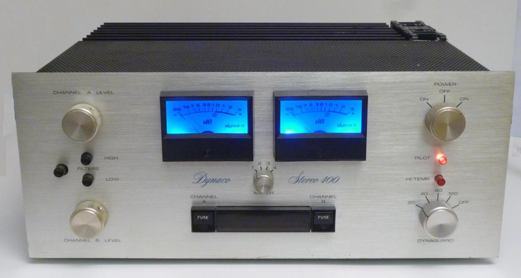
Phase Linear had the 700. Dynaco answered the challenge with the Stereo 400 power amplifier. It was conservatively rated at 200 WPC into eight Ohms. Massive heat-sinks even allowed it to pass the old FTC pre-conditioning tests. When it came out, that much power in an amplifier seemed scary to many people, particularly Dynaco. That's why they included the Dynaguard power limiting system...to keep speakers from going up in flames.
After its introduction, various options and variations came to be available, though they were based on the same basic design. (Some of this information is courtesy of posters on Audiokarma.org).
The first link is a very clean scan of the Stereo 400 Assembly manual.
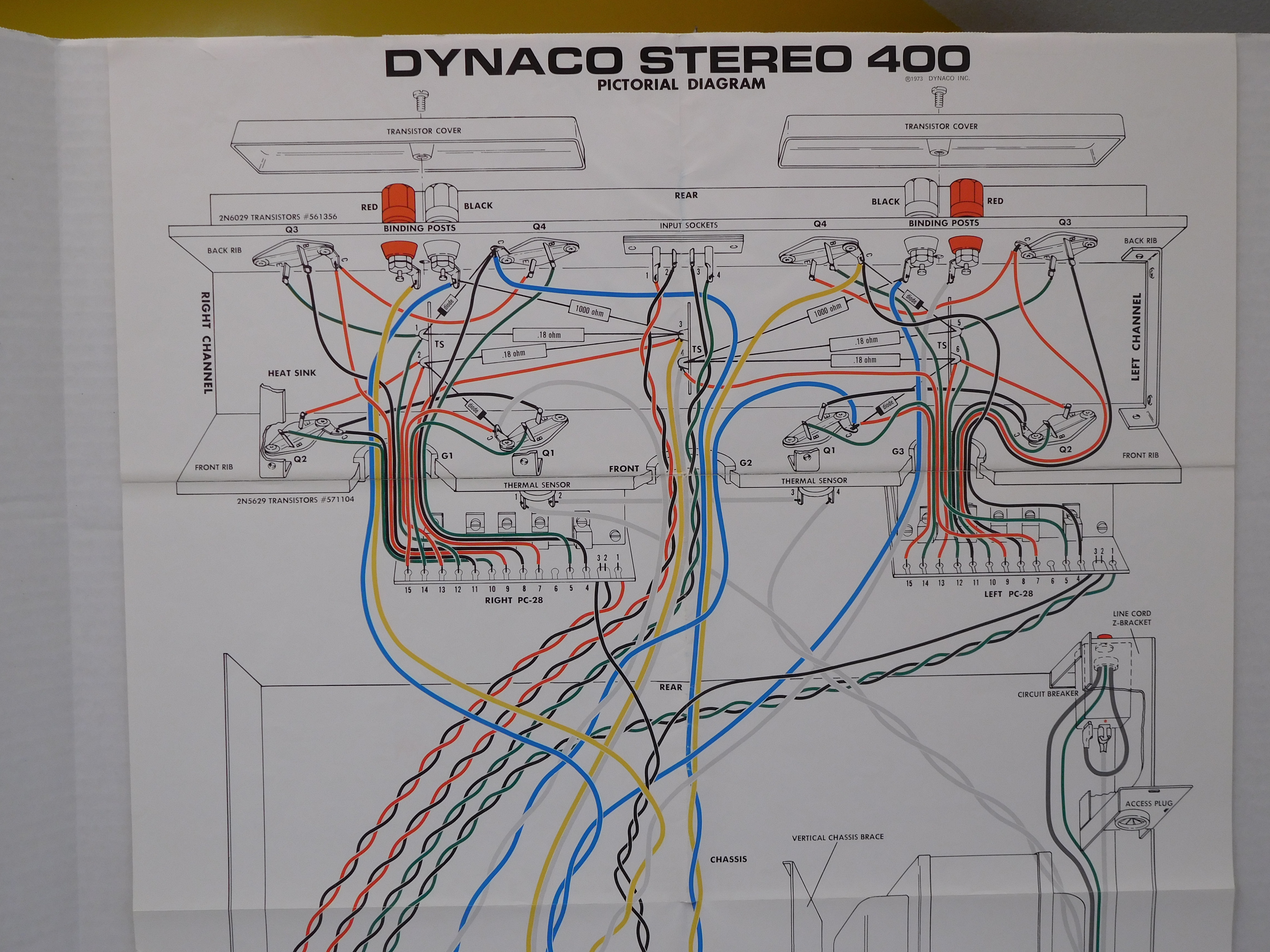
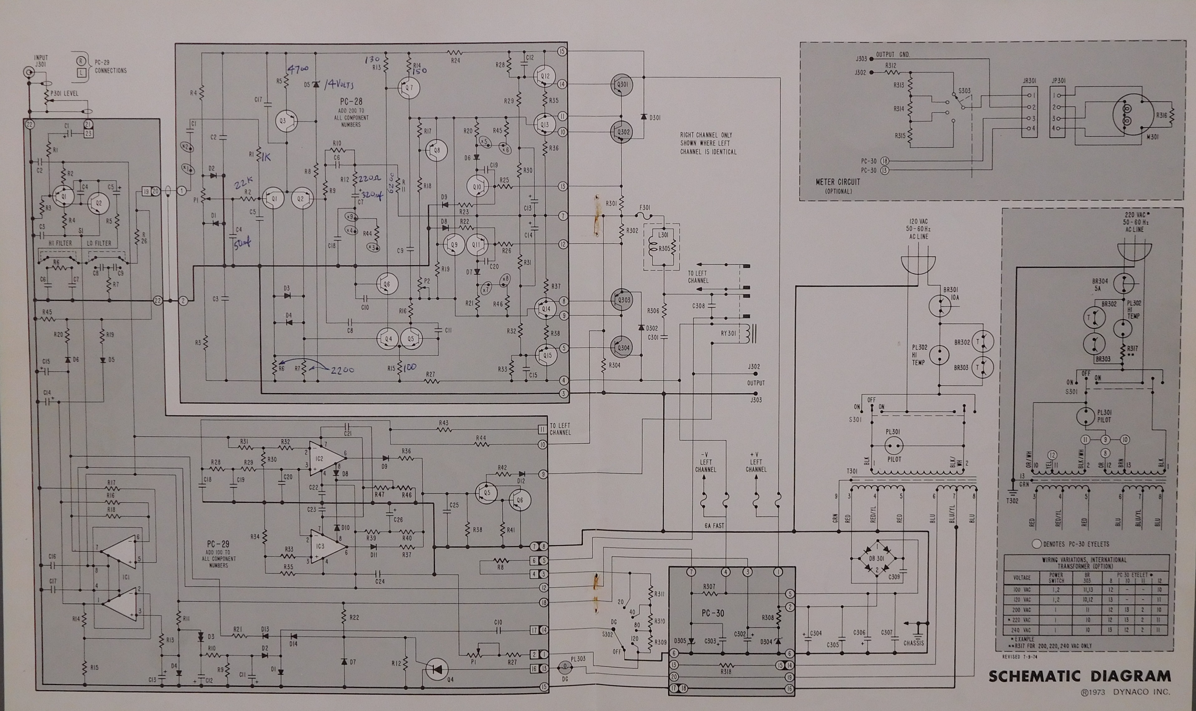
The next links have three pictures of the large fold-out wiring diagram. It's too big to scan, and pretty tough to find online. Each picture is a large file, about 4 Mb each. If you zoom in, you can see all the detail you need to see.
The Stereo 416 followed the 400. It was a beast with 8 output transistors per channel, or 16 output transistors in total, thus the "416". You could also order the C-100 capacitor bank (assembled only) to add 100,000 uF to the power supply. It had a two speed fan, and was rated down to 2 Ohm loads (450 Watts at 2 Ohms, single channel driven, 1% distortion). It had LED power metering with a meter range switch, and you could bypass both the Dynaguard and level controls. It was the no-holds barred power amp.
Tom P of California was kind enough to share a scan from his collection of a document that covers both the Stereo 416 and the PAT-5 Bifet.
Here's a scan of the Stereo 416 assembly manual, and of the large fold-out.
The Stereo 410 was the basic 200 WPC amp. No Dynaguard, level controls, or meters, and a price advertised at "under a dollar per watt".
Once again, Tom P of California was kind enough to share a scan from his collection of a document that covers the Stereo 410.
This copy of the Stereo 410 Assembly and User's manual was formerly posted on Tubes4hifi's website.
Here's another version of the Stereo 410 manual (77 MB file size), from my collection.Stereo 410 Assembly and User's manual, DMJ collection.
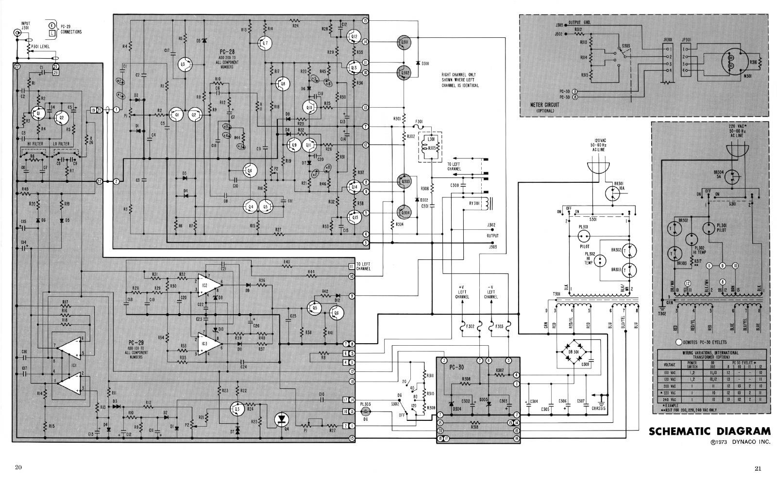
Here's the STEREO 410 schematic with nominal DC voltages added. This should be a help to troubleshooting for the Stereo 400 and 410, and perhaps to some degree, for the 416.
There are two rather different versions of the Dynaguard board, but maddeningly, both are called PC-29. I found this out recently when I realized a boyhood ambition to own a Stereo 400. This one has the metering kit. The left channel Dynaguard light was permanently on. I redrew the Dynaguard schematic in LTSpice to better understand its working. Upon looking at the PC-29 in my Stereo 400, I quickly found that there were significant differences from the manual I had. That manual was purchased in a pilgrammage taken to Dynaco in Blackwood, NJ in the mid 1970's.
A quick trip to Greg Dunne's Dynaco Site site showed me a different PC-29 schematic. Contrast this with the PC-29 schematic in the manual that I have. Note: It's a large, high res file, at about 5 Megs, so will take a little while to download.
The speaker relay had grown intermittement. It's a large, beefy relay with a 48 Volt coil and big contacts rated at 15 Amps. Still, with age, I guess some oxidation had corrupted the contacts. The most blameless suggestion I could find was to clean it with laser printer paper soaked with 90% isopropyl alcohol. I pulled the alcohol soaked paper through the contacts on December 29, 2012. We'll see how long it lasts.
You can now get a replacement speaker relay kit for the Stereo 400. It uses a pair of sealed relays with contacts rated at 16 Amps. This exceeds the original relay's current carrying capacity. We've named this the RY301 kit after its designation in Stereo 400 schematics. Here's the Stereo 400 Relay Kit Manual. Order the Stereo 400 Relay Kit.
The original transistors are essentially unobtainable. However, ONSEMI does make a modern equivalents that are a little faster and stronger than the originals. The MJ15003 and MJ15004 are the NPN and PNP replacements you need. They come in the same package as the original transistors, and so will drop right in. I have a small stash of these transistors. Feel free to drop me an email (dan@updatemydynaco.com) if you'd like to buy some from me. As of this writing (6/27/2025) the transistors were in stock at Mouser. You'll also want to get new insulating mounting pads. They electrically isolate the transistor case from the grounded heat-sink while maximizing heat removal.
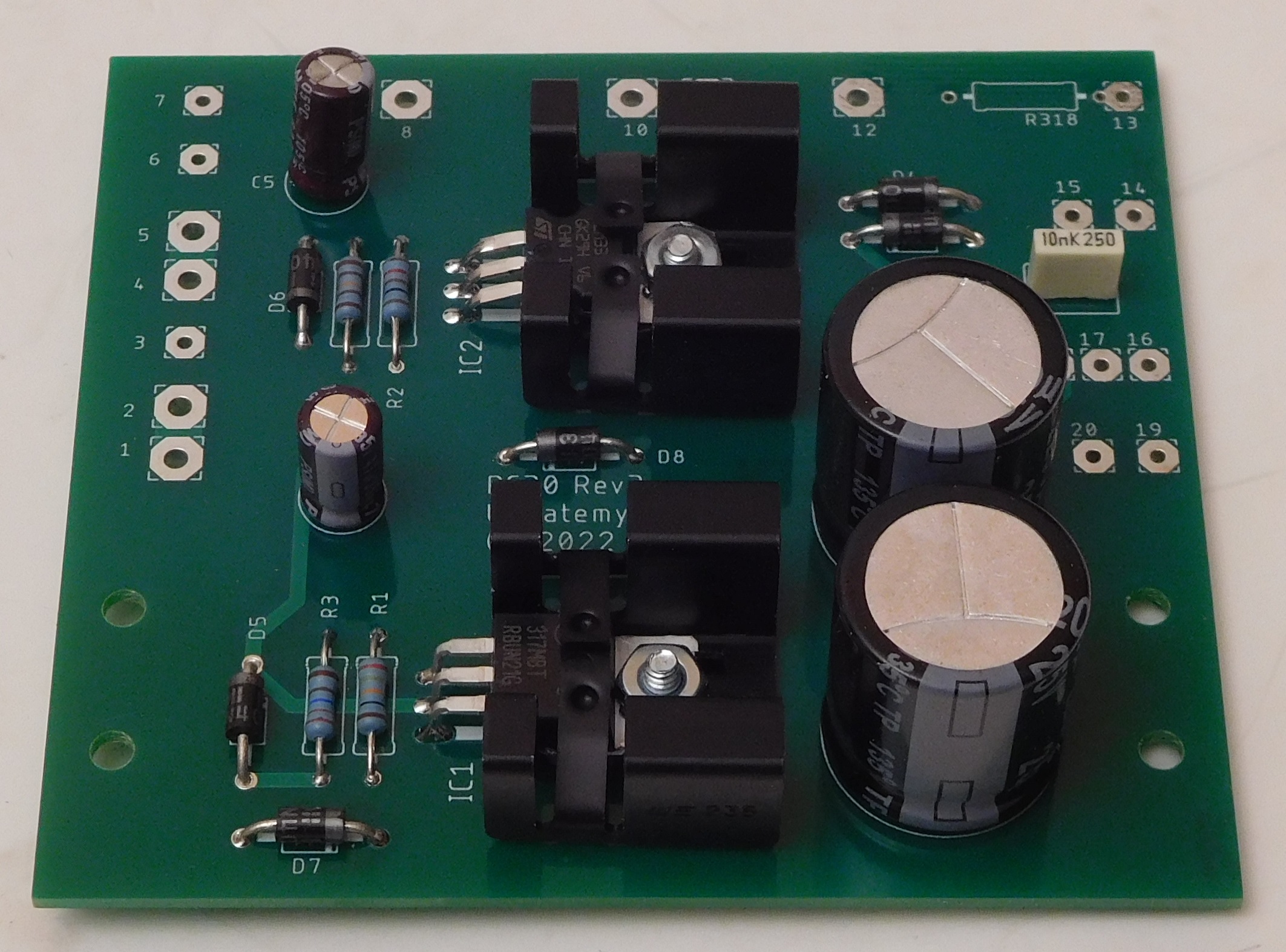
The PC-30 is a power supply for all the low-level sections of the Stereo 400. For some reason, the original implementation was kind of old fashioned, made with large power resistors run from the +/-75 volt rails with Zener diodes to regulate the +/-13V supply. Between those two resistors, the dissipation is a total of 11 Watts! That was enough to put burned spots on the PCBs. At most, the useful available power from this configuration is 1.75 Watts.
Now, someone on the design team was a bit forward looking, because the Stereo 400 also included low voltage windings on the transformer. They went essentially unused in the original design. In our new PC-30 design, we take advantage of the low voltage windings to produce pristine plus and minus 13 volts, while wasting perhaps 1 or 2 Watts, not 11 Watts! Keeping 10 Watts of constant heat out of the Stereo 400 is actually a very nice thing to do.
If you'd like your Stereo 400 to live long and prosper, we recommend installing our PC-30 board when you upgrade your Stereo 400.
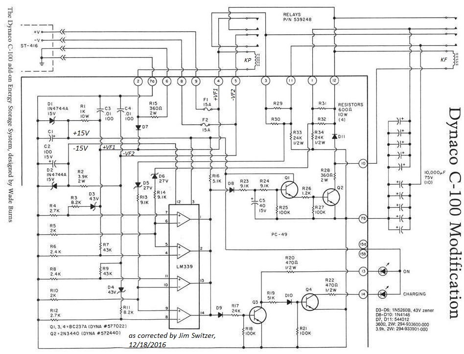
Large filter caps in the power supply hold up the power supply rails even when the going gets rough. The Stereo 400 and 416 were there at the birth of the "Super Amps" and the start of the microfarad wars. Manufacturers started throwing 10's of thousands of microfarads into their power supplies, all in the name of better bass. The C-100 capacitor bank was the ultimate answer to the microfarad wars. You could add a C-100 to a Stereo 400 or a 416.
The schematic shown below contains revisions and corrections pointed out to me by Jim Switzer in an email on 12/17/2016. I added a few more annotations that make the schematic a bit easier to analyze and understand. In the course of that, I've written a circuit description that contains a mystery, so the schematic might still have an error.
One channel had continuous Dynaguard indication, although it wasn't actually limiting. Q3 on the PC-29 had gone bad. I replaced it with a 2N3904, and it worked fine. A quick check showed reasonable indication, but I think that Dynaguard is probably not much needed.
The retaining tangs for one of the speaker fuse holders had broken. Everything with a Stereo 400 is a bit of an adventure. This was, too. The enclosed video shows the process of changing the fuse holder. I have the fuse-holders in stock, though it's not an item listed in the store. Just send me an email and we can work it out.
The beautiful blue VU meters are illuminated by small incandescent bulbs powered by AC from low voltage taps on the transformer. Each meter has two bulbs. The right meter had one bulb that still worked. Both left meter bulbs were blown out. The low voltage transformer winding puts out 15 volts RMS (open circuit) between the grounded center-tap and the winding that drives the meter bulbs.
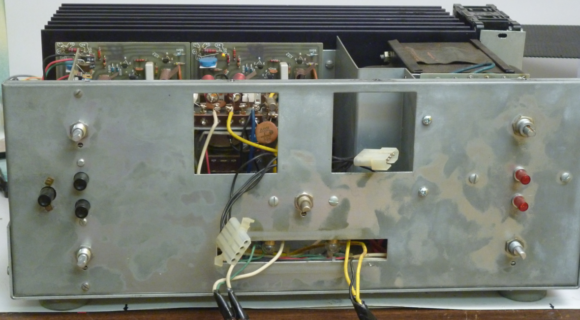
Here we've just posted a number of pictures of a partially disassembled Stereo 400. This is one that I'm doing a bit of restoration on. The main cosmetic thing is that the meter lamps are pretty well gone. I think I might be able to put some white LED's in there. Or, I wonder...is this the place for a Blue Light Kit?
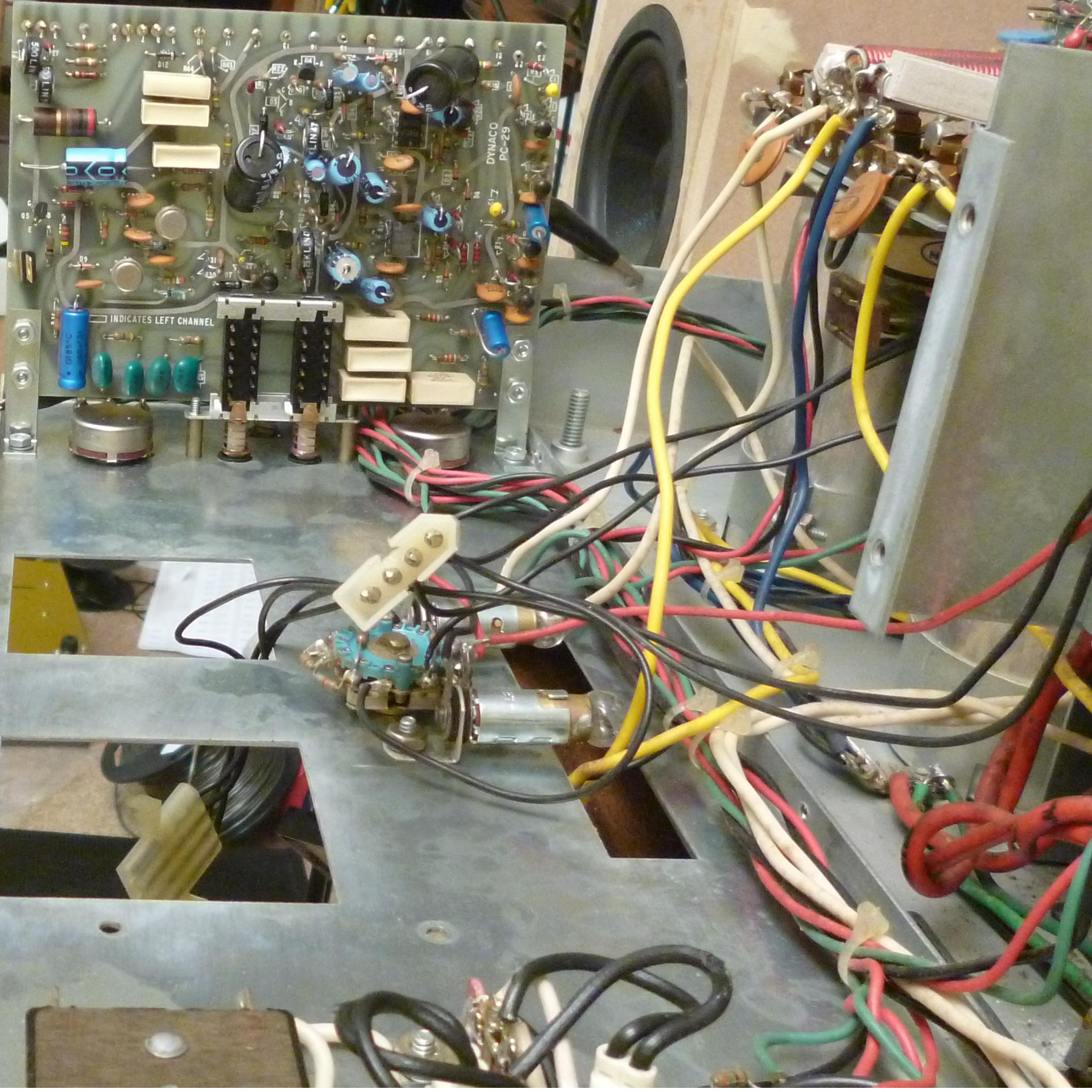
Front Panel Folded Down
Front view, escutcheon plate removed
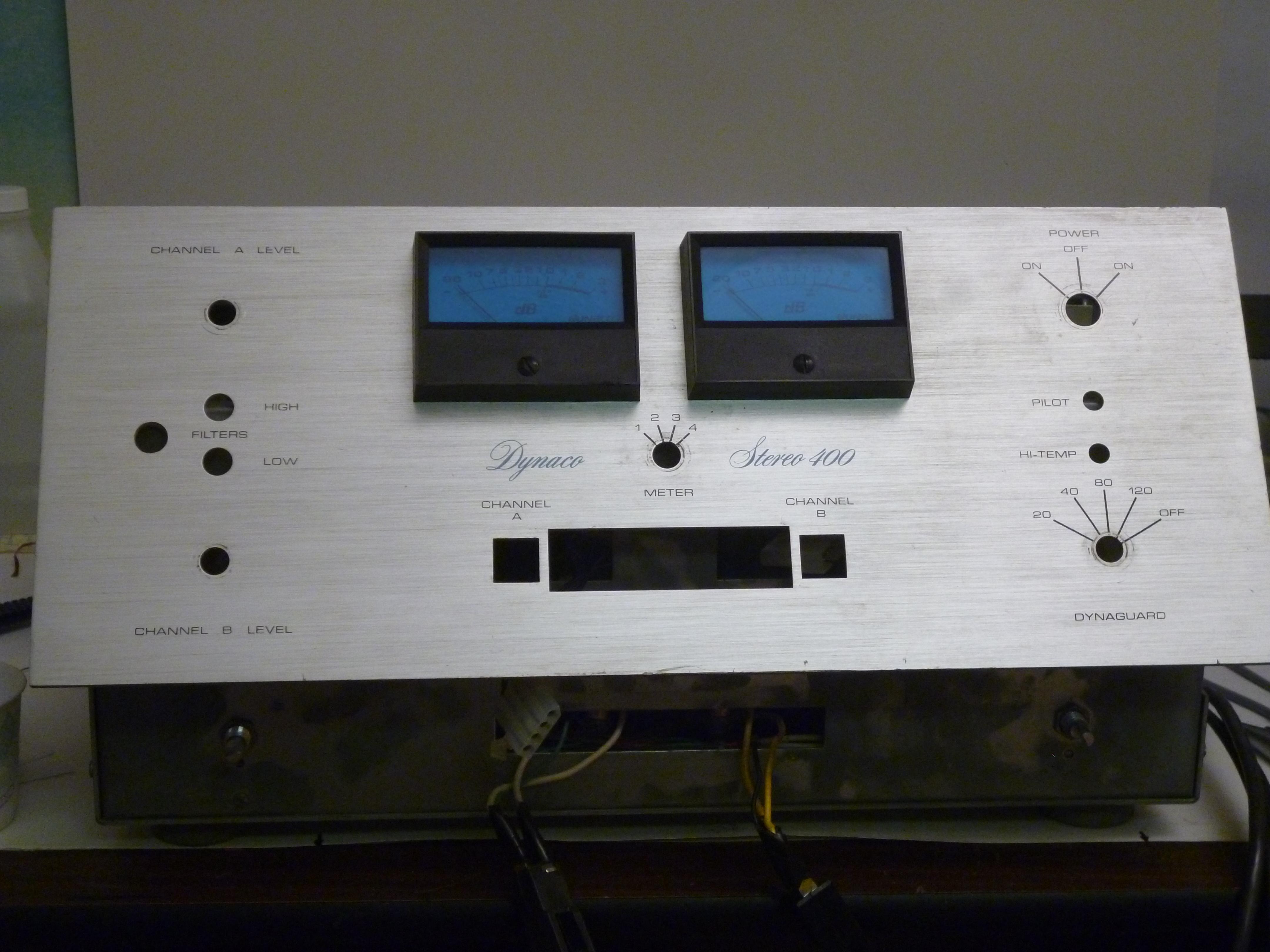
closeup of escutcheon plate
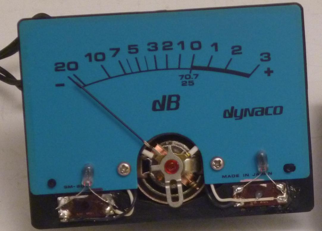
Closeup of meter with bezel removed, showing illuminating lamps
We replaced the original incandescent lamps with blue light kits. The assembly method is a bit modified from the classic way we've done it in the case of Neon lamp replacement. We used a single 470 Ohm 1/4 Watt resistor with each blue light kit. We then used 1 blue light board to replace each of the incandescent lamps. This is shown in the next picture.
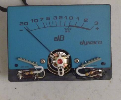
Stereo 400 Meter with blue light kits replacing incandescent lamps
The next picture shows the amp with the meters replaced, and the blue light kits installed in the meters. The room has normal daylight illumination.
Stereo 400, meters lit by blue light kits
The next picture shows the amp with the meters replaced, and the blue light kits installed in the meters in a dark room.
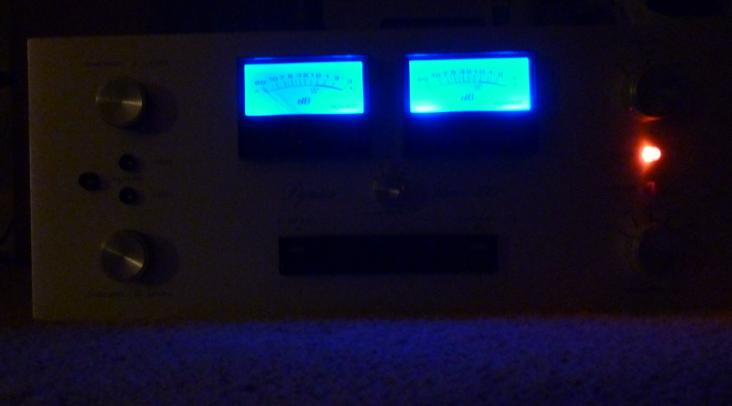
Blue Light illuminated meters in a dark room
This picture shows the values, listed on the schematic, for the Stereo 410. The design is very similar to the Stereo 400, and might be used as a guide for the 400 also. The Stereo 416 is similar, but it has double sets of output transistors.
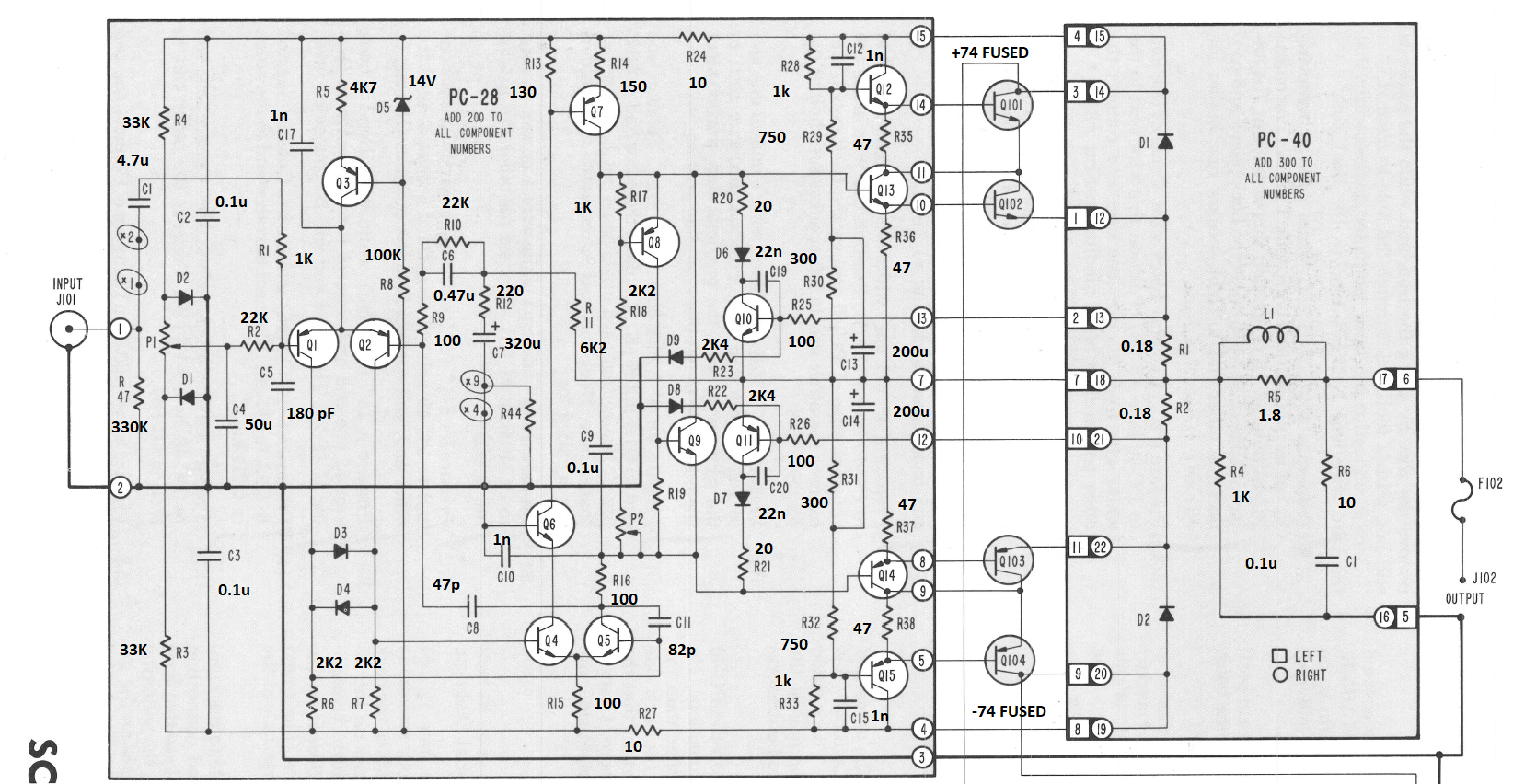
Stereo 410 schematic with annotated values
This picture shows the values and voltages, listed on the schematic, for the Stereo 410. The design is very similar to the Stereo 400, and might be used as a guide for the 400 also. The Stereo 416 is similar, but it has double sets of output transistors. These voltages apply with no input signal, and the bias current adjusted for 75 mA in the output transistors. These voltages are a rough guide. In some places, small changes are not significant. In other places, like across R1 or R2, small changes might indicate large problems. Good luck, and hopefully the "magic smoke" will stay inside your power amp.
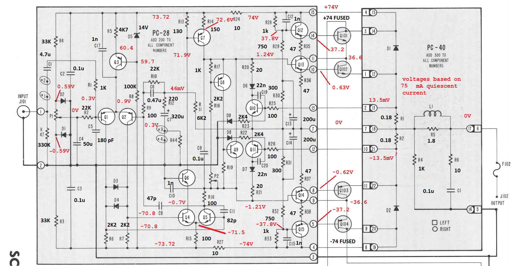
Stereo 410 schematic with annotated values and voltages
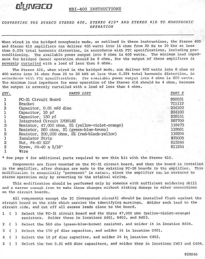
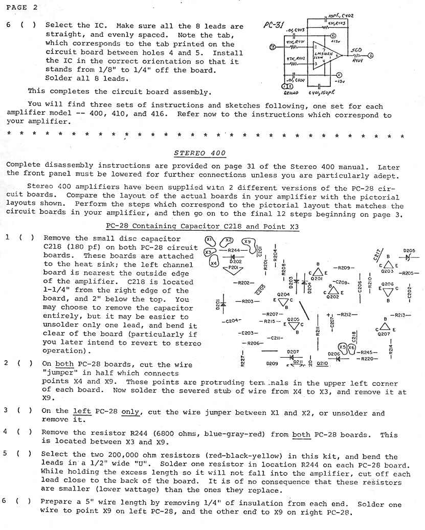
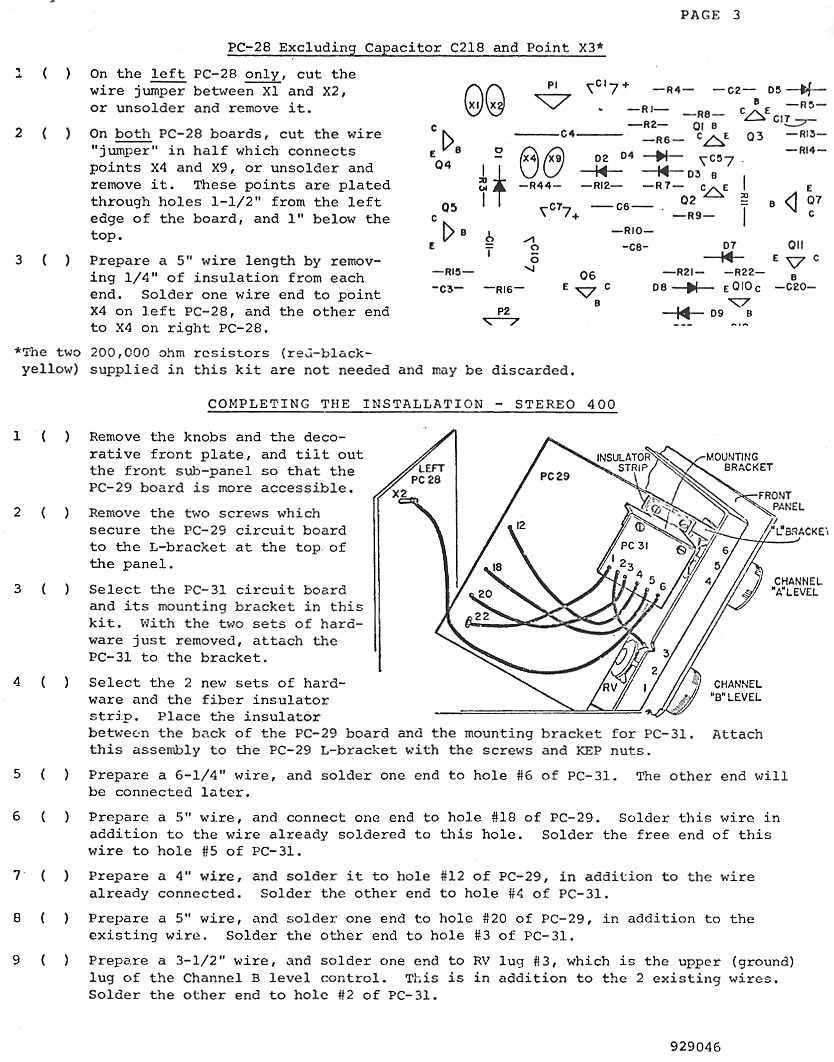
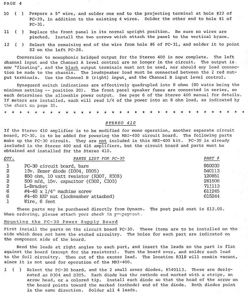
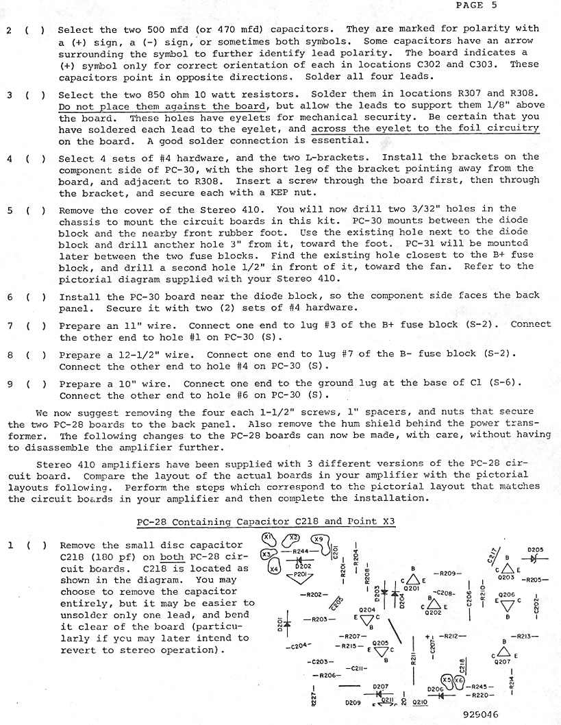
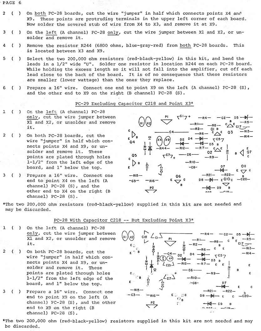
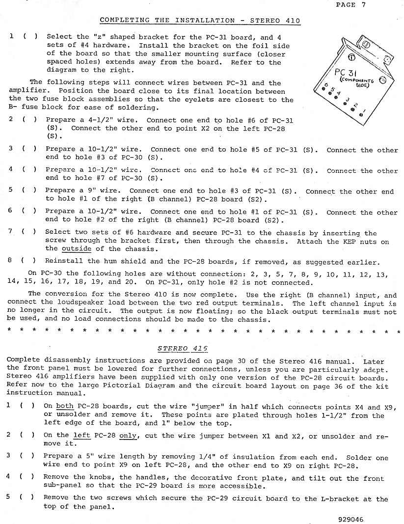
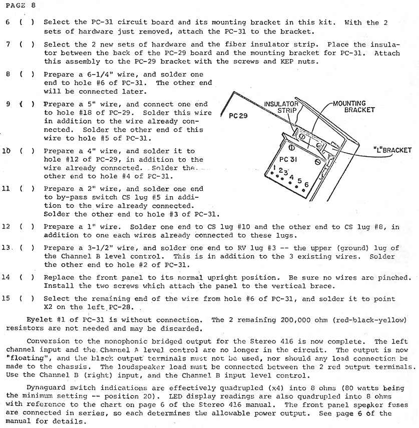
You could wire the amp for bridged mode operation. In that configuration, it was rated to produce (monophonic) 600 Watts into 8 Ohms. The MBI-400 document showed how to make the conversion.