Click here to return to the home page.
All About Signal Tracing
What is Signal Tracing?
You've often had the problem...You're putting signal into a piece of equipment, for example a preamp, but nothing is coming out! How can you possibly locate the problem? Signal Tracing is the answer.
Here's how it works. You put a signal into the device under test, then trace the signal as it progresses from input to output, looking for where the signal doesn't have the expected behavior. Signal tracing
requires two things:
- A signal source
- A signal measuring device
Signal Sources
The gold-standard for a signal source is a function generator that makes sine waves and perhaps square waves and triangle waves, where you can adjust both the amplitude and the frequency. However, the
gold standard implies parting with a certain amount of gold, so are there less expensive but still useful signal sources for signal tracing? Yes:
- You could download the test-tone files shown a little farther down on this page, and play them on your computer or tablet. Best of all, they're free!
- You could use a CD with test tones, played on your CD player
- You could download a tone generator from the net, but once the trial time expires, you have to pay for it.
- If you wanted a very low distortion 1 kHz sine wave and would like to build a kit, you could buy this kit.
Signal Measuring Devices
The gold standard for a signal measuring device is the oscilloscope. However, they are expensive, and take some skill to operate, so we'll list a couple of options here:
- AC volt-meter with a sensitive enough scale to be useful. A full-scale reading of 2 volts or less is necessary for most audio work. Why do I mention this? Some cheap meters just have a 200 Volts scale.
They are fine for measuring voltage from the wall-socket, but pretty useless for preamps.
- With a little thought, you can use your power-amp to signal trace, but that's a story for another day.
Stereo equipment has a built-in example
Let's say that the left channel is working, and the right channel is broken. If you're working on a piece of stereo equipment, then you have a built-in example. Apply signals to both channels, then work your way from
input to output. Compare the signal level seen at the right channel with the signal level seen at the left channel. At the point where those two readings diverge, you've localized the problem. You may not know exactly
what the problem is, but you will know what portion of the circuit is working, and which portion isn't.
Don't forget the simple stuff
Before you get too exotic, remember to check the simple stuff:
- Is the unit plugged in?
- Is the fuse good?
- Are the power supplies the voltages that you expect?
- Did you remember to connect, plug-in, and turn-on your signal source?
Signal Tracing: a PAT-5 Example
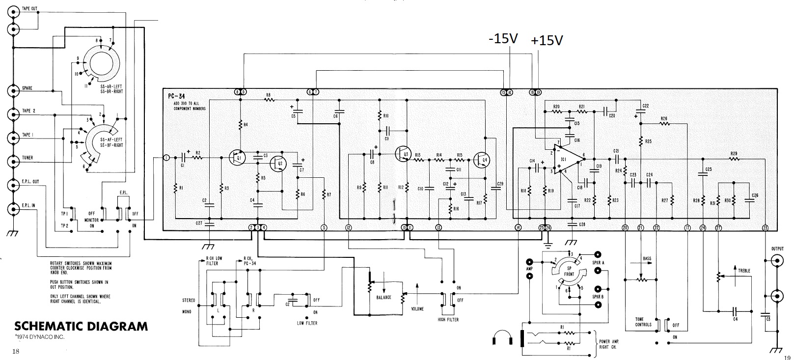
Assume that signals connected to the TUNER input aren't making it to the output. Here are the trouble-shooting steps you'd apply
- Make sure that the PAT-5 is powered. Be careful not to contact the 120 or 240 Volts inside the PAT5.
- Connect a signal source having a level of between about 100 mV and 1 volt (a little lower or a little higher is fine, also) to the TUNER input of the PAT-5 channel under test.
- Make sure that your signal source is really running. Make sure that the selector switch is in the TUNER position. Put your AC volt-meter right across the TUNER RCA jack on the PAT-5. Look for a reasonable
voltage, between 100 mV and 1 volt.
- Once that voltage is good, move on and measure the voltage between eyelet 1 and ground (eyelets 2, 3, and 4 are grounded, and so is the metal of the chassis, and so are the grounds of the RCA jacks)
- The voltage from eyelet 1 to ground should be a very close to the voltage that you measured on the RCA jack itself. If it isn't, then:
- Check the position of the Monitor Switch. It should be in the OFF (out) position.
- Check the position of the EPL siwtch. It should be in the OFF (out) position.
- If both switches are in the correct position then the problem might be
- broken switches or dirty switch contacts
- the fault is closer to the input jacks, work your way back toward the input jacks (thru the EPL switch, the Monitor switch, and the selector switch).
- If the voltage on eyelet 1 with respect to ground is good, then check the voltage on eyelet 5 with respect to ground. It should be about 90% of the voltage seen on eyelet 1.
- If it isn't, then the problem is likely between eyelet 1 and eyelet 5.
- If the voltage is good, then check at the ungrounded side of the balance control. The voltage there should be very nearly the same voltage as seen on pin 5.
- If it isn't, then check it along the way as it goes from eyelet 5 to the stereo mono switch, to the low filter switch.
- If it is good, then check the voltage on eyelet 14. Turn the volume control up all the way. The voltage you see should be very close to the voltage observed on Pin 5
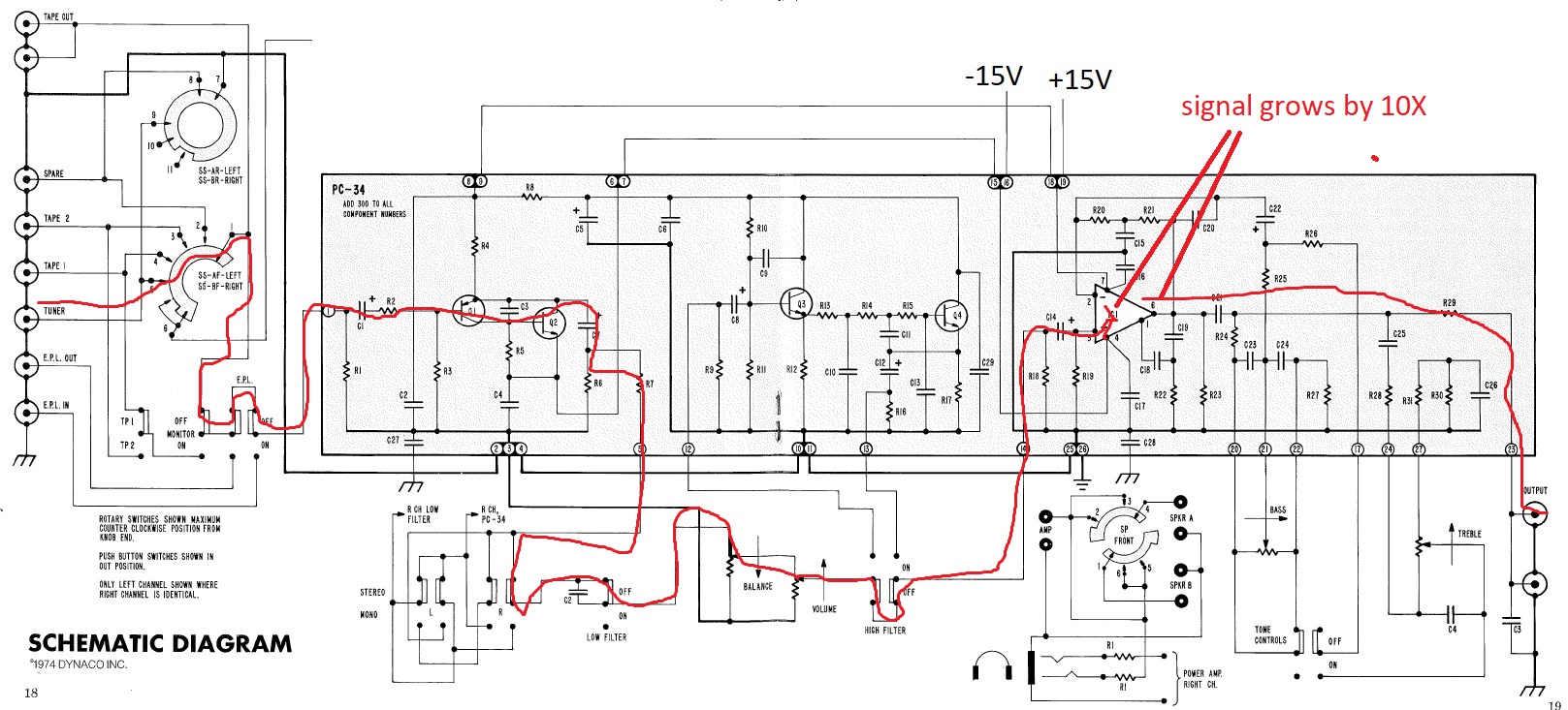
- Now, the gain of the output stage, IC1, is about a factor of 10. So, the voltage on eyelet 23 should be about 10 times the voltage on eyelet 14. This might be a good time to turn the
volume control down so there's only about 100 or 200 mV on pin 14. That then calls for a very manageable 1 or 2 Volts on pin 23.
- If you see nothing on pin 23, then walk your way back. Is there any signal on R29 where it meets C25? If so, then the high level stage is probably working.
- If not, then there might be a short to ground on eyelet 23.
Mostly, you'll find the signal flow goes input=>output and left=> right on the schematic page. I've drawn a "Family-Circle" style line from the Tuner input all the way thru to the output, showing
the basic path of the signal when all of the front panel buttons are in the out position.
Binary Search: The Quickest Way to Locate the Problem Area
After you've done this and thought through it enough times, something like the idea of the binary search will come to you. What is a binary search? It's a successive cutting the signal path in half to very
quickly sectionalize the problem. Here's an example:
- Apply a signal source at the input
- Measure the signal at the output. If it's good, you're done. If the signal is missing or otherwise bad, then find a point half-way through the signal path.
- Measure the signal at the half-way point. Is it good? Then you know that the input half of the circuits is good, and the output half is bad.
- Measure the signal at the 3/4 point, that's half-way between the half-way point and the output.
- Is the signal ok at the 3/4 point? Now either find a point 7/8 of the way thru the circuit, or given the short number of remaining possibilities, just step your way from the last good signal point towards the
bad signal point
In this way, you should be able to quickly find where the signal disappears, or is otherwise not correct.
Test Tone Files
You can download this zip file with test tones. The zipped file contains .wav files that should be compatible with any playback program on your computer.
Create a directory with a useful name, like TestTones, and then move the unzipped files to the TestTones directory.
Just pick the test tone frequency, level, and wave-shape
that you think would be most useful. Each file has a tone that lasts for 10 seconds, contains two channels (left and right, although sometimes one or the other is silent), and is sampled at 44.1 kHz with 16 bit
resolution. Need a longer playback than 10 seconds? Press the auto-repeat button on your player. There will be a small hiccup when the file repeats, but most of the ten seconds will be clean.
Here is a list of the file names, and a description of their contents.
- 1kHzSineBOTHNeg3dBFS.wav, a 1 kHz sine wave in both Left and Right channels, at a level that is 3 dB below full scale (maximum) output.
- 1kHzSineBOTHNeg23dBFS.wav, a 1 kHz sine wave in both Left and Right channels, at a level that is 23 dB below full scale (maximum) output.
- 1kHzSineLeftNeg3dBFS.wav, a 1 kHz sine wave in only the left channel, at a level that is 3 dB below full scale (maximum) output.
- 1kHzSineLeftNeg23dBFS.wav, a 1 kHz sine wave in only the left channel, at a level that is 23 dB below full scale (maximum) output.
- 1kHzSineRightNeg3dBFS.wav, a 1 kHz sine wave in only the right channel, at a level that is 3 dB below full scale (maximum) output.
- 1kHzSineLeftNeg23dBFS.wav, a 1 kHz sine wave in only the right channel, at a level that is 23 dB below full scale (maximum) output.
Would you like me to add some test tone that isn't currently there? Send me email and describe your request.
Test Tone Files for Frequency Response Testing
You can download this zip file with test tones constructed for the purpose of doing frequency response runs. The zipped file contains .wav files that should be
compatible with any playback program on your computer.
Create a directory with a useful name, like FrequencyResponseTestTones, and then move the unzipped files to the FrequencyResponseTestTones directory.
All of these tones are at equal amplitudes on LEFT and RIGHT Channel, that amplitude having peaks 3 dB below full scale. The thing that differs amongst the files is their frequency. The frequencies are 20 Hz, 40 Hz,
80 Hz, 160 Hz, 320 Hz, 640 Hz, 1 kHz, 2 kHz, 4 kHz, 8 kHz and 16 kHz. The file names are pretty clear about the frequency in the file.
The most accurate way to get a frequency response reading is to use the same meter to measure both the input to the system and the output from the system. This tends to cancel many kinds of errors, but it isn't perfectly foolproof.
Each file has a tone that lasts for 10 seconds
A Handy Cable
Lots of sound cards, PCs, and tablets use a 1/8" RCA jack for their audio output. Most Stereo equipment uses RCA jacks for I/O. You'll probably need to order a 3-conductor 1/8" jack to dual RCA jack converter.
You can them by searching with "1/8" to dual RCA" on either Amazon or Google.

Return to Updatemydynaco Home Page